
- Форум
- Техника КВ/УКВ
- Усилители мощности
- ACOM
- Acom-1000

-
11.10.2021, 14:08
#226
QRP
Разобрал трансивер, управление Send идет через сдвиговый регистр, в котором на выходе стоят транзисторы с открытым стоком, видимо пришел конец этой микросхеме.
Спасибо большое за помощь!
-
11.10.2021, 14:52
#227
Коротковолновик
Сообщение от UA9SJR
Send срабатывает на всех бэндах, ниже диапазона 40 метров, то есть работает на 160, 80 и 40 м….
offtop/
В Flex 6000 серии, срабатывание PTT задается в настройках по диапазонно.
-
13.10.2021, 06:46
#228
Малоактивен
Сообщение от UA9SJR
Спасибо большое за помощь!
Что в итоге, неисправность или настройки трансивера ?
-
11.02.2022, 13:52
#229
Low Power
Здоровья всем. Не подскажите как сбросить старые показания ошибки и запустить его на новое тестирование? Пытаюсь включить, а он сразу показывает старую ошибку и не запускается…
-
11.02.2022, 20:45
#230
Very High Power
Сообщение от RU9TR
Здоровья всем. Не подскажите как сбросить старые показания ошибки и запустить его на новое тестирование? Пытаюсь включить, а он сразу показывает старую ошибку и не запускается…
При каждом включении усилитель делает тест. Он не один, их несколько. Если первый тест не проходит, усилитель не включится.
Каждый раз ошибка выводится на дисплей под своим порядковым номером. Ошибка может быть она и та же, но номер будет разный.
Для начала, надо знать какая ошибка, и тогда можно что то предполагать.
-
11.02.2022, 22:41
#231
Начинающий
Сообщение от UA3AIF
При каждом включении усилитель делает тест. Он не один, их несколько. Если первый тест не проходит, усилитель не включится.
Каждый раз ошибка выводится на дисплей под своим порядковым номером. Ошибка может быть она и та же, но номер будет разный.
Для начала, надо знать какая ошибка, и тогда можно что то предполагать.Все правильно Андрей!
Писал ему на другом форуме, но ответа нет…ACOM 1000
до встречи!
-
03.04.2022, 14:24
#232
QRP
Коллеги добрый день !
Имеется ACOM `1000. При включение перестал запускаться. Пишет ошибку : Auto protection: PN07
Последнюю работу ум завершил нормально! А на след. день вот такая бяка. Что с этим делать ? Спасибо!
-
03.04.2022, 14:39
#233
SWL EXTRA CLASS.
Возможно Вам поможет это с сайта e-HAM:
Я работаю на ACOM 1000 с октября 2001 года, что означает 13 лет безотказной работы и упорной работы на радиолюбителях (очень активно, состязательно, QSK). В этом году случилось так, что в апреле 2014 года ПА перешел в режим автозащиты с кодом PN07. После контакта с Val LZ1VB и дальнейшей помощи и подробных инструкций по электронной почте я смог найти неисправный диод в мосту высокого напряжения. Получил заказанные 4 новых и более мощных диода в течение 3-х дней и провел Счастливую Пасху! Спасибо за этот отличный сервис.
Сейчас, 6 октября, УМ снова ушел в режим автозащиты с кодом TR2B. Кажется, что он становится старше, как и я. Опять же, Вэл оказал исключительную помощь, предоставив подробные инструкции по измерению и визуальной проверке по электронной почте. В итоге сломалось вакуумное реле и опять доставили в течении 3-х рабочих дней. Я хотел бы поблагодарить Вала за этот яркий пример обслуживания клиентов и желаю ему всего наилучшего в будущем! де Ахим, DL1DAW двух
-
03.04.2022, 14:46
#234
Big Gun
Откройте…
Скорее всего, вздуло конденсатор электролит по 24 В (3300х35).
-
03.04.2022, 15:17
#235
High Power
Развалился родимый .
UA3GUX Казалось бы наоборот от щедрости добреют ,но удивительный народ чем больше Гулливер дает ,тем лилипуты злее.
-
04.04.2022, 13:53
#236
QRP
Сообщение от RV3MP
Откройте…
Скорее всего, вздуло конденсатор электролит по 24 В (3300х35).Добрый день! Смотреть в БП ?
-
04.04.2022, 14:21
#237
Big Gun
Сообщение от RU3ADA Andy
Auto protection: PN07
Судя по коду ошибки
PN0 – тесты, сделанные во время процедуры включения усилителя (POWER-ON), до того, как подано высокое напряжение (HV is ON)
Т.е. он не может толком включиться.
Гляньте (лучше сразу поменять) все электролиты. БП низковольтный собран по хитрой схеме. Сдыхает С5 и начинается полный бардак.
На сколько помню, то (если смотреть спереди) левый дальний угол платы БП. Конденсатор большой… не промахнетесь.
-
04.04.2022, 14:39
#238
QRP
Сообщение от RV3MP
Судя по коду ошибки
PN0 – тесты, сделанные во время процедуры включения усилителя (POWER-ON),до того, как подано высокое напряжение
(HV is ON)
Т.е. он не может толком включиться.
Гляньте (лучше сразу поменять) все электролиты. БП низковольтный собран по хитрой схеме. Сдыхает С5 и начинается полный бардак.
На сколько помню, то (если смотреть спереди) левый дальний угол платы БП. Конденсатор большой… не промахнетесь.Спасибо! Буду на выходных смотреть ! Отпишу по итогу !
-
26.04.2022, 11:59
#239
Standart Power
Дисплей АСОМ 1000
Вопрос к знатокам — не стало подсветки дисплея на усилителе,
периодически появляется. Информация , конечно, плохо читается.
Может кто встречался с таким дефектом?
-
26.04.2022, 23:17
#240
Very High Power
Дисплей отработал свой ресурс.
К счастью полно таких дисплеев.
Снимите его и подберите такой же в ближайшей лавке.


Похожие темы
-
Ответов: 25
Последнее сообщение: 06.12.2010, 08:09
-
Ответов: 92
Последнее сообщение: 02.09.2010, 04:41
-
Ответов: 14
Последнее сообщение: 11.01.2009, 19:23
-
Ответов: 3
Последнее сообщение: 29.12.2008, 10:15
-
Acom
от RA3CQ в разделе КВ аппаратура
Ответов: 48
Последнее сообщение: 02.10.2004, 22:04
Please, see Section
5.3 Reading Auto-protection Signatures
signatures. You can decode them using the information below.
The signatures are structured in two lines, three groups by six symbols for every one event of auto-
protection. The last event is numbered as 1A-1B pair of lines, and the oldest one is 7A-7B.
The meaning of the first group is as follows:
a)
nA — the number of the trip;
b)
Next three symbols mean the following:
PN0
Tests made during Power-On procedure, before HV is ON;
PN2
Tests made during Power-On procedure, after HV is ON and one second after step-
start relay is closed;
SB0
Tests made in Stand-By, during the warm-up period or while entering Stand By (from
Operate);
SB2
Tests made during Stand-By, after the warm-up period;
PR0
Tests made while entering Operate;
PR2
Tests made during Operate;
TR0
Antenna relay tests made while changing from Tx to Rx (during Operate);
TR2
Antenna relay tests made while changing from Rx to Tx (during Operate);
TR4
Antenna relay tests made during Tx (Operate mode);
TR6
Antenna relay tests made during Rx (Operate mode).
c)
The last symbol of the first group designates the kind of the input parameter, which caused
the protection circuit to trip. The abbreviations in brackets below are the signal
names/designations according to the CONTROL PCB electrical schematic diagram and signal
type:
1
Peak forward power (pfwd, analogue)
2
Reflected power (rfl, analogue)
3
Input (drive) power (inp, analogue)
4
Peak anode alternate voltage (paav, analogue)
5
Screen grid current (g2c, analogue)
6
Plate current (ipm, analogue)
7
High voltage (hvm, analogue)
8
Exhaust air temperature (temp, analogue)
9
Drive power exists (*GRIDRF, logic)
Page 30 of 36 | S e c t i o n MAINTENANCE
User’s Manual | ACOM 1000 | HF + 6m Linear Amplifier
for the method of reading the auto-protection
August 2020
-
Contents
-
Table of Contents
-
Troubleshooting
-
Bookmarks
Quick Links
OU T S TANDING HF P OWER PRODUC T S
ACOM 1000
HF + 6m
Linear Amplifier
User’s Manual
Installation, Operation
and Maintenance
August 2020
Related Manuals for Acom 1000
Summary of Contents for Acom 1000
-
Page 1
OU T S TANDING HF P OWER PRODUC T S ACOM 1000 HF + 6m Linear Amplifier User’s Manual Installation, Operation and Maintenance August 2020… -
Page 2
User’s Manual | ACOM 1000 | HF + 6m Linear Amplifier This manual is for electronic distribution mainly. If you have it on paper and you no longer need it, please, recycle it! The latest versions of our User’s Manuals are available at www.acom-bg.com… -
Page 3: About Documentation
ACOM products and services. Further, this User’s Manual is provided AS IS and ACOM shall not be liable for possible errors contained herein.
-
Page 4
User’s Manual | ACOM 1000 | HF + 6m Linear Amplifier Title of Documentation ACOM 1000 HF + 6m Linear Amplifier User’s Manual Installation, Operation and Maintenance Type of Documentation User’s Manual Purpose of Documentation This manual explains Installation, Operation and Maintenance of the ACOM 1000 HF + 6m Linear Amplifier. -
Page 5: Table Of Contents
User’s Manual | ACOM 1000 | HF + 6m Linear Amplifier Contents ABOUT DOCUMENTATION ……………………..3 GENERAL INFORMATION ……………………… 7 1.1. Introduction and Description ………………….7 1.2. Owner Assistance ……………………..7 1.3. Equipment Supplied ……………………7 1.4. Features ……………………….8 1.5.
-
Page 6
User’s Manual | ACOM 1000 | HF + 6m Linear Amplifier SPECIFICATIONS ……………………….32 7.1. Parameters ………………………. 32 7.2. Functions ……………………….33 7.3. Storage and Shipment ……………………34 Figures Figure 2-1 Connections ……………………… 13 Figure 3-1 ACOM 1000 Display and Control ………………..16 Figure 3-2 Information Screens and Control Functions Structure ………….. -
Page 7: General Information
Congratulations on purchasing one of the finest HF amplifiers in the world today. ACOM is pleased that you have chosen one of our products, and we will endeavor to provide you with the information and support you need to enjoy your purchase for many years.
-
Page 8: Features
Easy maintenance. Signatures of the amplifier internal status are stored in a nonvolatile memory for 7 most recent auto protection trips. This information can be forwarded to your dealer for diagnostics. Using an EXCEL APPLICATION (available from ACOM or your dealer free of charge) and a PC you can decode the signatures by yourself, too.
-
Page 9: Safety Considerations, Explicit Definitions
1.5. Safety Considerations, Explicit Definitions The ACOM 1000 HF + 6 meters Linear Amplifier is a Safety Class I unit. The third grounding lead of its mains cord (which is colored yellow with two green stripes) and the ground stud on the rear panel of the amplifier (marked GND) must be connected to the station’s grounding system for safe operation.
-
Page 10
User’s Manual | ACOM 1000 | HF + 6m Linear Amplifier PRECAUTIONS: D A N G E R ! H I G H V O L T A G E ! The amplifier works with high voltages up to 3000V, which are LETHAL! For your safety, pull the amplifier power plug out of the mains wall outlet and WAIT AT LEAST 30 minutes EACH TIME BEFORE you remove the cover of the amplifier. -
Page 11: Installation
N O T E Before you install your amplifier, thoroughly read this manual. First, carefully inspect the cardboard carton and its contents for physical damage. ACOM ships amplifiers in highly protected containers, but it cannot assure that mistreatment by shippers will not occur.
-
Page 12: Amplifier Location Selection
User’s Manual | ACOM 1000 | HF + 6m Linear Amplifier 2.3. Amplifier Location Selection N O T E The weight of the unit is about 22kg, which should preferably be handled by two persons. Position the amplifier near the place where it will be used. You will need an easy access to the command knobs and indicator’s area, as well as to the rear panel cabling.
-
Page 13: Figure 2-1 Connections
User’s Manual | ACOM 1000 | HF + 6m Linear Amplifier Figure 2-1 Connections First, connect the ground stud of the amplifier (on the rear panel, marked GND) to the station’s grounding system (see Figure 2-1 Connections Connect a coaxial cable with a PL-259 plug from the transceiver output to the amplifier rear panel RF INPUT socket.
-
Page 14
User’s Manual | ACOM 1000 | HF + 6m Linear Amplifier N O T E Your amplifier will not work if KEY-IN is not connected properly. Transceiver producers give different names to this output and they are for instance TX- GND, SEND, T/R-LINE, etc. -
Page 15: Installation Of External Fan
User’s Manual | ACOM 1000 | HF + 6m Linear Amplifier It is preferable that you use the wall outlet closest to the source. The installation leads should be at least 1.5mm² (AWG 15 or SWG 17). Check if the respective fuses can handle current up to 10A as well, and whether the voltage corresponds to the voltage for which the amplifier is set (see Section 2.2 Line Voltage…
-
Page 16: Power On, Controls And Indicators
«LINE» on the rear panel (see ). The LED indicator above the red ON/OFF button Figure 2-1 Connections located on the front panel must light red and «ACOM 1000» will appear on the OLED (see Figure 3-1 ACOM 1000 Display and Control Figure 3-1 ACOM 1000 Display and Control You’ll note that the upper line of the OLED always reads the peak forward power, even in STBY mode.
-
Page 17: Figure 3-2 Information Screens And Control Functions Structure
User’s Manual | ACOM 1000 | HF + 6m Linear Amplifier In this position (called OFF LINE hereafter) only the micro-controller is operational, while the amplifier itself is still turned off (the tube is not powered at all). The control of the amplifier is accessible during OFF LINE and ON LINE states, each having several…
-
Page 18: Operation
User’s Manual | ACOM 1000 | HF + 6m Linear Amplifier 4. OPERATION Operation of the amplifier is simplified due to the TRI tuning aid, Auto-Operate function, and automatic protection system, so you’ll be able to begin using the amplifier immediately after the installation.
-
Page 19: Changing Operate And Standby Modes
User’s Manual | ACOM 1000 | HF + 6m Linear Amplifier After the indicated period expires, the ON/OFF button stops flashing and lights green constantly. If the auto-operate function is selected to ON (see Section ), the green 5.2 Auto-Operate enabling and disabling OPER LED lights too.
-
Page 20
User’s Manual | ACOM 1000 | HF + 6m Linear Amplifier The amplifier can operate safely as long as the REFLECTED POWER is LESS THAN 300W. Also, impedance matching is assured for loads presenting a VSWR of up to 3:1. Although for some loads and bands, matching is possible at even higher VSWR levels, the drive power must be reduced to prevent the REFLECTED POWER from exceeding 300W. -
Page 21: Table 4-1 Approximate Tuning Preset
User’s Manual | ACOM 1000 | HF + 6m Linear Amplifier We recommend that you tune-up at the center frequencies of the preferred frequency band. First select the band switch (never with RF applied!). Then use (see ) in order to…
-
Page 22: Table 4-2 Using Tri Tuning Aid
User’s Manual | ACOM 1000 | HF + 6m Linear Amplifier Tuning Procedure While a continuous (CW) signal at the desired frequency is still applied: Look at the upper scale (forward power). Obtain maximum power using the upper (TUNE) •…
-
Page 23: On Line Information Screens And Control Functions
User’s Manual | ACOM 1000 | HF + 6m Linear Amplifier Tuning to the left of the center would lead to the opposite: less gain and more power attainable. Of course, this requires more drive power, more plate current, and more plate heat, which shortens tube’s-expected life, as its cathode would be faster exhausted.
-
Page 24: Auto-Protection System
User’s Manual | ACOM 1000 | HF + 6m Linear Amplifier 4.5. Auto-Protection System When any abnormal condition is detected, the amplifier will evaluate the risk and may use three different degrees of protection, depending on the nature of the problem. Each event is accompanied by a text telling you the reason.
-
Page 25: Off Line Operation
User’s Manual | ACOM 1000 | HF + 6m Linear Amplifier 5. OFF LINE OPERATION There is a control function and 14 information screens available in this state of the amplifier. You can enable/disable the Auto-Operate feature. You can also list the auto — protection signatures. The tube is not powered at all (only the micro-controller is active) during these operations.
-
Page 26: Reading Auto-Protection Signatures
User’s Manual | ACOM 1000 | HF + 6m Linear Amplifier 5.3. Reading Auto-protection Signatures On every Hard Fault protection trip of the amplifier, signature information is stored in its nonvolatile memory. The 7 most recent auto-protection trip signatures related to the amplifier internal status are stored there, which you can copy and forward to your dealer for diagnostics.
-
Page 27: Maintenance
User’s Manual | ACOM 1000 | HF + 6m Linear Amplifier 6. MAINTENANCE 6.1. Cleaning W A R N I N G Do not use solvents for cleaning — they may be dangerous both for you and for the amplifier paint or plastics.
-
Page 28: Acom 1000 Simplified Schematic Diagram
Many software-derived protections are based on this information. N O T E Забележка! Note! Detailed electrical schematic diagrams are available from ACOM or from your dealer on request. Page 28 of 36 | S e c t i o n MAINTENANCE August 2020…
-
Page 29: Figure 6-1 Acom 1500 Simplified Schematic Diagram
User’s Manual | ACOM 1000 | HF + 6m Linear Amplifier Figure 6-1 ACOM 1500 Simplified Schematic Diagram August 2020 S e c t i o n MAINTENANCE | Page 29 of 36…
-
Page 30: Troubleshooting
User’s Manual | ACOM 1000 | HF + 6m Linear Amplifier 6.5. Troubleshooting Please, see Section for the method of reading the auto-protection 5.3 Reading Auto-protection Signatures signatures. You can decode them using the information below. The signatures are structured in two lines, three groups by six symbols for every one event of auto- protection.
-
Page 31
N O T E Additional information is available from ACOM or from your dealer on how to interpret these values. Using an Excel application available from ACOM or your dealer free of charge, and a PC, you can decode these signatures. -
Page 32: Specifications
User’s Manual | ACOM 1000 | HF + 6m Linear Amplifier 7. SPECIFICATIONS 7.1. Parameters Frequency Coverage: All amateur bands 1.8-54MHz, extensions and/or changes on request; Power Output: 1000W PEP or continuous carrier, no mode limit; In continuous carrier modes (RTTY etc.) for transmissions longer than 15 minutes (up to several hours depending on ambient temperature), the external auxiliary fan must be mounted.
-
Page 33: Functions
User’s Manual | ACOM 1000 | HF + 6m Linear Amplifier 7.2. Functions Antenna Impedance Matching Process: plate-load True Resistance Indicator (TRI) aided; T/R System: QSK operation with built-in, vacuum RF antenna relay (special quiet installation)’ Protections: Cover interlock for operator’s safety;…
-
Page 34: Storage And Shipment
User’s Manual | ACOM 1000 | HF + 6m Linear Amplifier 7.3. Storage and Shipment W A R N I N G Should you need to transport the amplifier, use the original packing as described below. First, switch off the amplifier. Pull the mains plug out of the outlet. Disconnect all cables from the rear panel of the amplifier (remove the ground connection the last).
-
Page 35
User’s Manual | ACOM 1000 | HF + 6m Linear Amplifier This manual is for electronic distribution mainly. If you have it on paper and you no longer need it, please, recycle it! The latest versions of our User’s Manuals are available at www.acom-bg.com… -
Page 36
о support@acom-bg.com www.acom-bg.com ACOM and the ACOM logo are registered trademarks of ACOM Ltd. in many countries, including the EU and United States. I The used images are illustrative only. Subject to change without notice. I Printed in Bulgaria. All rights reserved. I Design and content by ACOM Ltd. I August 2020.
Предложите, как улучшить StudyLib
(Для жалоб на нарушения авторских прав, используйте
другую форму
)
Ваш е-мэйл
Заполните, если хотите получить ответ
Оцените наш проект
1
2
3
4
5

Exhibit 8 1 —17
International, Inc.
Exhibit 8: User’s Manual
External Radio Frequency
Power Amplifier ACOM 1000
Model 1000
157 Horse Pond Road, Sudbury, MA 01776
Tel: (978) 440-7555
Fax: (978) 440-9080
e-mail: aa1nd@aol.com
Exhibit 8 2 —17
TABLE OF CONTENTS
1. GENERAL INFORMATION ………………………………………………………………………………………………………………2
1-1. INTRODUCTION AND DESCRIPTION………………………………………………………………………………………………………2
1-2. OWNER ASSISTANCE ………………………………………………………………………………………………………………………..2
1-3. EQUIPMENT SUPPLIED ………………………………………………………………………………………………………………………3
1-4. FEATURES………………………………………………………………………………………………………………………………………3
1-5. SAFETY CONSIDERATIONS, EXPLICIT DEFINITIONS …………………………………………………………………………………3
2. INSTALLATION………………………………………………………………………………………………………………………………4
2-1. UNPACKING AND INITIAL INSPECTION………………………………………………………………………………………………….4
2-2. LINE VOLTAGE SELECTION………………………………………………………………………………………………………………..4
2-3. AMPLIFIER LOCATION SELECTION ………………………………………………………………………………………………………4
2-4. CONNECTIONS ………………………………………………………………………………………………………………………………..5
2-5. INSTALLATION OF EXTERNAL FAN………………………………………………………………………………………………………6
3. POWER ON, CONTROLS AND INDICATORS…………………………………………………………………………………….6
4. OPERATION……………………………………………………………………………………………………………………………………8
4-1. TURNING ON AND OFF…………………………………………………………………………………………………………………….8
4-2. CHANGING OPERATE AND STANDBY MODES…………………………………………………………………………………………9
4-3. TUNING …………………………………………………………………………………………………………………………………………9
4-4 ON LINE INFORMATION SCREENS AND CONTROL FUNCTIONS. ……………………………………………………………….11
4-5 AUTO-PROTECTION SYSTEM……………………………………………………………………………………………………………..11
5. OFF LINE OPERATION ………………………………………………………………………………………………………………….11
5-1 CONTRAST AND BACKLIGHTING CONTROL …………………………………………………………………………………………..12
5-2 AUTO-OPERATE ENABLING AND DISABLING …………………………………………………………………………………………12
5-3. READING AUTO—PROTECTION SIGNATURES …………………………………………………………………………………………12
6. MAINTENANCE…………………………………………………………………………………………………………………………….12
6-1. CLEANING ……………………………………………………………………………………………………………………………………12
6-2. FUSES REPLACEMENT …………………………………………………………………………………………………………………….12
6-3. TUBE REPLACEMENT………………………………………………………………………………………………………………………13
6-4. THE ACOM1000 SIMPLIFIED SCHEMATIC DIAGRAM…………………………………………………………………………….14
6-5. TROUBLESHOOTING ……………………………………………………………………………………………………………………….15
7. SPECIFICATIONS ………………………………………………………………………………………………………………………….15
7-1. PARAMETERS………………………………………………………………………………………………………………………………..15
7-2. FUNCTIONS…………………………………………………………………………………………………………………………………..16
7-3. STORAGE AND SHIPMENT ………………………………………………………………………………………………………………..16
1. GENERAL INFORMATION
1-1. Introduction and Description
This manual explains the installation, operation, and maintenance of the ACOM1000 HF+6 meters linear amplifier.
The ACOM1000 is a complete and self-contained linear amplifier that covers all amateurs bands from 1.8 through
54MHz and provides over 1000W-output power with less than 60W-exciter drive. Antenna VSWR up to 3:1 is acceptable
at full power. Tuning is substantially simplified by a plate-load True Resistance Indicator (TRI) and by an automatically
controlled input attenuator. Operating parameters are displayed by a multi-functional backlighted Liquid Crystal Display.
Full break-in transmit/receive switching (QSK) is standard.
1-2. Owner Assistance
If assistance is needed, you should contact your local dealer first. If you still have an issue you need to discuss with one
of ACOM’s specialists, the contact information is as follows: fax + 359 2 230 116, tel. + 359 2 229 147, e-mail
acom@aster.net or by mail: bul. Gornobanski Nr.151, 1330 Sofia, Bulgaria.
Exhibit 8 3 —17
1-3. Equipment Supplied
The ACOM1000 amplifier and this manual are shipped in a cardboard carton.
1-4. Features
• Easy to operate. The TRI is a powerful tuning aid which, together with the automatically controlled input attenuator,
helps the operator to quickly and precisely match antennas (5-10 seconds typically). The auto-operate function (when
enabled) maintains the amplifier in OPERATE mode for you, thus saving manual operations and time.
• No heavy outboard antenna tuners required for antenna VSWR up to 3:1 (and higher on some bands). Your
amplifier will perform the functions of an antenna tuner, thus enabling you change antennas faster and use them over a
wider frequency range (saving tuning time).
• An amplifier that is both user-friendly, and that looks after itself. It is designed to safely withstand up to 500W
reflected power, up to 100 milliseconds duration of drive spikes, drive RF «tails» after a PTT or KEY release, operator’s
inadvertent tuning errors etc. It would also not cease to function with a «soft» AC line and would deliver more than half
power at only 75% of nominal mains voltage. It would withstand up to 10 milliseconds (down to zero) voltage drops, and
up to +15% line voltage spikes, which is important particularly when used at field days, Dxpeditions, and other portable
events.
• LCD comment display. All amplifier status indications are explained via detailed text displayed on the dot matrix
backlighted liquid crystal display (LCD). The upper-line’s strip on the LCD always reads directly peak forward power. For
OPERATE, attenuator-on, and ON/OFF conditions are provided LED indicators.
• Easy maintenance. Signatures of the amplifier internal status are stored in a nonvolatile memory for 7 most recent
auto protection trips. This information can be forwarded to your dealer for diagnostics. Using an EXCEL APPLICATION
(available from ACOM or your dealer free of charge) and a PC you can decode the signatures by yourself too.
• Less noise in the shack: the input bypassing and the vacuum antenna relays are virtually silent even in QSK CW
mode due to their special mounting.
• Less QRM and improved Electro Magnetic Compatibility during tuning. Antenna matching can be achieved in less
than 10 seconds at a quarter of nominal output power.
• Operates without special signals from the transceiver — «ground on TX» and 60W RF drive power are sufficient.
• Broadband input matching circuit resulting in very good load to the transceiver over the entire spectrum from
1.8MHz up to 54MHz.
• Uses a single 4CX800A (GU74B) Svetlana high-performance ceramic-metal tetrode with plate dissipation of 800W
(forced air cooling, grid-driven).
• Permanent monitoring and protection of plate and grid voltages and currents, as well as of the exhaust air
temperature. The Bias Optimizer decreases the heat dissipated from the tube, and there is automatic protection against
overheating in accordance with the specifications of the tube producer.
• An output RF Arc protection is employed. It safeguards the amplifier, antenna, antenna selector, and tuner against
severe damage in case of possible break down.
• High voltage power supply inrush current protection, which eliminates the danger of affecting sensitive devices,
connected to the same mains circuit (important when used portable). The amplifier can be configured for 5 nominal line
voltages: 200, 210, 220, 230, and 240VAC, 50 or 60Hz (100, 110, and 120VAC on request).
• Continuous measuring and/or selectable monitoring of 12 most important parameters of the amplifier, exciter and
antennas via LCD.
• The amplifier can be shipped with 10 and 12 meters capability disabled as required by the FCC for US users.
Contact your dealer about enabling those bands.
1-5. Safety Considerations, Explicit Definitions
The ACOM1000 HF+6 meters Linear Amplifier is a Safety Class I unit. The third grounding lead of its mains cord (which
is colored yellow with two green stripes) and the ground stud on the rear panel of the amplifier, (marked GND) must be
connected to the station’s grounding system for safe operation.
The amplifier is designed to meet international safety standards and complies with CE safety and electromagnetic
compatibility requirements, as well as FCC regulations.
This operating manual contains information, precautions, indications for cautions and warnings which must be followed
by the user to ensure safe operation and to keep the ACOM1000 in safe operating condition.
PRECAUTIONS:
The EXPLICIT DEFINITIONS described below apply to this operating manual:
W A R N I N G notes call attention to a procedure which, if not correctly performed, could result in personal injury, fire
hazard or electric shock.
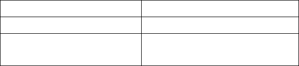
Exhibit 8 4 —17
C A U T I O N notes call attention to a procedure which, if not correctly performed, could result in equipment damage,
not only in the amplifier.
N O T E notes call attention to a procedure which, if not correctly performed, could result in inconvenience.
W A R N I N G HIGH VOLTAGE!
The amplifier works with high voltages up to 3000V, which are LETHAL! Also, for your safety, pull the amplifier power
plug out of the mains wall outlet and WAIT AT LEAST 30 minutes EACH TIME BEFORE you remove the cover of the
amplifier. Do not touch any part inside while the amplifier is open because some residual voltages may still be present.
W A R N I N G HIGH VOLTAGE!
NEVER ALLOW ANYONE, ESPECIALLY CHILDREN,
to push anything into holes in the case — this will cause electric shock. NEVER TOUCH AN ANTENNA during
transmission — this may result in an electric shock or burn. NEVER EXPOSE the amplifier to rain, snow or any liquids.
AVOID placing the amplifier in excessively dusty environments or in direct sunlight. DO NOT OBSTRUCT AIR INTAKE
(rear panel) and EXHAUST (top cover) areas of the amplifier. Keep a minimum distance of 10cm (4 inches) to the intake
and 50cm (20 inches) to the exhaust.
W A R N I N G
Do not undertake on your own repairs or changes in hardware or software of the amplifier. Otherwise you may endanger
your or other’s health and life or damage the amplifier and the equipment connected with it, not covered by warranty.
The manufacturer is not liable for another’s actions and responsibility shall be assumed by the doer.
C A U T I O N
To avoid damage (not covered under warranty) read the Installation — Section 2 of this operating manual carefully. If you
have any doubts about the installation, operation or safeties of the amplifier please consult your dealer.
2. INSTALLATION
2-1. Unpacking and Initial Inspection
N O T E
Before you start to install the amplifier, thoroughly read this manual. First, carefully inspect the cardboard carton and its
contents for physical damage. If damage is noticed, notify your dealer immediately. Delay may infringe carrier’s warranty
conditions. Keep all packing for possible future transportation!
2-2. Line Voltage Selection
C A U T I O N
To avoid damage (not covered under warranty), check carefully if the voltage for which the amplifier is set corresponds
to your mains nominal voltage.
Normally the amplifier is supplied set for a nominal line voltage of 240V. There might be exceptions in cases of special
delivery and then the voltage set is noted in the Table of Individual Data (Table 2-1). If your power line has a different
nominal voltage, it will be necessary for you to contact your dealer.
AMP s/n
Tube s/n
Voltage Selector VAC
TABLE 2-1. ACOM 1000 INDIVIDUAL DATA
2-3. Amplifier Location Selection
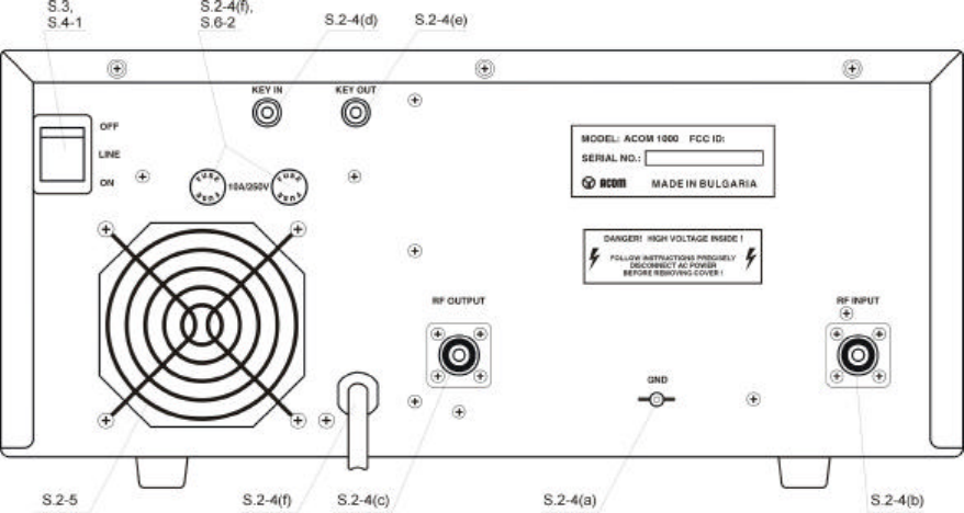
Exhibit 8 5 —17
C A U T I O N
The weight of the unit is about 18kg, which should preferably be handled by two persons.
Position the amplifier near the place where it will be used. You’ll need an easy access to the command knobs and
indicator’s area, as well as to the rear panel cabling.
No magnetic-field sensitive devices should be located next to the right side of the amplifier as its power transformer is
located there. It’s best to position it to the right of your transceiver. No temperature sensitive devices should be located
above the exhaust hot air area, so don’t push it under a shelf. You may prefer to use the bottom scales of both variable
capacitor knobs (TUNE and LOAD) if you install it on a shelf. DO NOT OBSTRUCT AIR INTAKE (rear panel) and
EXHAUST (top cover) areas of the amplifier. Keep a minimum distance of 10cm (4 inches) to the intake and 50cm (20
inches) to the exhaust.
2-4. Connections
Connection to your station must be accomplished in the order described below, before you apply mains voltage to the
amplifier.
W A R N I N G
Note that the grounding system may have to withstand currents over 10A with insignificant voltage drop on it. Therefore,
it may be necessary to improve it considerably, i.e. to become less resistive, with heavier leads and lower-resistive
ground path. The grounding leads should be at least 4mm2 (AWG 11 or SWG 13).
Fig.2-1 Connections
a) First, connect the ground stud of the amplifier (on the rear panel, marked GND) to the station’s grounding system
(Fig.2-1).
b) Connect a coaxial cable with a PL-259 plug from the transceiver output to the amplifier rear panel RF INPUT socket.
C A U T I O N
If this is the first time you will use a power amplifier in your station, pay attention to the coaxial cable type from the
amplifier’s output. It must handle the increased power safely, particularly on 10 and 6 meters bands. We recommend
you use RG213 or better. Check the same for the antenna selector and tuner as well as the antenna itself (especially
multi-band trap antennas).
c) Connect a coaxial cable from the amplifier output (on the rear panel, marked RF OUTPUT) with a PL-259 plug to the
antenna selector or tuner or to the antenna for the respective band.
d) Run a cable terminated in a Phono (RCA) connector from the transceiver socket providing «ground on transmit» to the
amplifier rear panel KEY-IN socket.
Exhibit 8 6 —17
N O T E
Your amplifier will not work if KEY-IN is not connected properly.
Transceiver producers give different names to this output and they are for instance TX-GND, SEND, T/R-LINE, etc.
Some transceivers require that «ground on transmit» is implemented via a software command, or by changing the setting
of a switch on the rear panel, or interior of the transceiver. Check your transceiver’s manual.
e) The KEY-OUT socket on the rear panel provides an extra control signal from the amplifier to the transceiver. It could
be used to improve the transmit/receive switching safety.
If your transceiver has a suitable input that disables transmission, we recommend that you connect it with a cable
terminated in a Phono (RCA) connector to the KEY-OUT socket of the amplifier. Transceiver producers give different
names to this input and they are for instance TX-INHIBIT, MUTE, LINEAR, etc. Check your transceiver’s manual or
consult your dealer.
If your transceiver does not have such input, don’t worry — the amplifier will function normally, as well and then the KEY-
OUT may remain unused.
f) Preparation of wall outlet for the amplifier.
W A R N I N G
If your amplifier is only fitted with one mains fuse, it is suitable for 0-220…240 VAC electricity supplies ONLY (these
supplies are standard in the European Community). Your dealer will check that your amplifier is correctly fused before it
is shipped to you. Customers should check with a qualified electrician if the amplifier is to be used outside the country in
which it was purchased.
Due to the different standards in different countries, the mains plug is supplied and mounted by the dealer. He connects
to the mains cord end a standard mains supply plug which meets the Safety Class I units standard in your country. The
ground lead of the amplifier’s power cord is colored yellow with two green stripes and the blue and brown leads are
active. When the amplifier is to be used with only one mains fuse, it is connected in series with the brown lead, which
must be the active. If you have any doubts about the correct way of connecting the wires, consult your dealer.
W A R N I N G
Before connecting the amplifier to your mains supply, be sure that the supply is correctly wired, and is adequate for the
current drawn by the amplifier (up to 10A). Make certain that the grounding lead is connected properly in the wall outlet
for the amplifier.
It is preferable that you use the wall outlet closest to the source. The installation leads should be at least 1.5mm2 (AWG
15 or SWG 17). Check if the respective fuses can handle current up to 10A, as well, as if the voltage corresponds to the
voltage for which the amplifier is set (S.2-2). If you connect the amplifier to a different mains outlet, be sure that you
check it, too.
Make sure the main Power Switch on the rear panel is in OFF position and insert amplifier’s mains plug into the wall
outlet prepared for it. The amplifier remains switched off.
2-5. Installation of External Fan
This fan (Fig. 2-1) is not necessary in SSB and CW modes, nor in continuous carrier modes (RTTY, SSTV etc.) with
carrier down times of maximum 15 minutes and a subsequent pause of 3 minutes. For higher duties or ambient
temperatures the fan is recommended. The auxiliary fan (92x92mm) must be brushless type, 2…5W/24VDC. It may be
installed by your dealer or by the manufacturer on request.
3. POWER ON, CONTROLS AND INDICATORS
C A U T I O N
Do not turn the amplifier on for at least 2 hours after unpacking it in the room where it will be used. Pay particular
attention when you move it from a very cold into a very warm place — condensation is likely and this could result in
damage to the high voltage circuits. In such a case, wait at least 4 hours. A similar effect can occur after a rapid
warming of the operating room (for instance after switching on a powerful heater in a cold shack).
C A U T I O N
Exhibit 8 7 —17
To avoid damage (not covered under warranty) carefully check that the voltage for which the amplifier is set corresponds
to your mains nominal voltage (see S.2-2 and table 2-1).
After following all instructions in S.2, you can turn ON the main power switch marked “LINE” on the rear panel (Fig.2-1).
The red LED indicator above the red ON/OFF button located on the front panel must light red and a black inscription
«ACOM1000» will appear on the LCD (Fig.3-1):
Fig.3-1 ACOM1000 Display and Control
You’ll note that the upper line of the LCD always reads directly peak forward power, even while the tube is not driven.
The 1200W scale resolution is 10W per bar, dots division weight is 60W, and figures are multiple to 300W. Note also
that levels below 20W may be not detected.
N O T E
If the characters on the LCD are dim or not readable, please follow the method of LCD contrast and backlighting
adjustment described in S.5-1.
In this position (called OFF LINE hereafter) only the micro-controller is operational, while the amplifier itself is still turned
off (the tube is not powered at all).
The control of the amplifier is accessible during OFF LINE and ON LINE states, each having several information screens
and control functions (see Fig.3-2):
Exhibit 8 8 —17
POWER ON S.3
OFF LINE S.5 (ON/OFF S4.1) ON LINE S.4
(NEXT or PREV) (PREV+NEXT) (PREV+NEXT)
(+2sec)
INFORMATION S.4-4
Forward Power
Reflected Power Tuning S.4-3 LCD adj. S.5-1
(PREV+NEXT) S.5-1 (OPER) S.5-3 Output Power TRI
Contrast 1…9 (PREV) List of Antenna VSWR
Back-light 1…5 (NEXT) Auto-Prot. Drive RF Power (PREV+NEXT)
Signatures RF Power Gain Auto-Operate S.5-2
(PREV)—(NEXT) Plate Current
(PREV+NEXT) S.5-2 High Voltage
Auto-Operate OFF (PREV) Plate RF Peak
Auto-Operate ON (NEXT) Screen Current
DC Power Input
Exh. Air Temp.
Fig.3-2 Information Screens and Control Functions Structure
The OPER button alternatively changes operate and standby modes (S.4-2) while ON LINE. Please note that Auto-
Operate might be enabled. The same button activates signature list while OFF LINE.
The PREV and NEXT buttons change information screens or select control functions (S.4-4) for both OFF LINE and ON
LINE.
The ON/OFF button alternatively switches OFF LINE and ON LINE states of the amplifier.
You can proceed in one of two directions:
a) You can use the OFF LINE information screens and control functions. They refer to the auto — protection signatures
list, LCD contrast and backlighting control, as well as the Auto-Operate feature. This is described in S5.
b) You can turn on the amplifier and begin the warm-up sequence. After 2.5 minutes you may tune and start operating
the amplifier and you can use the ON LINE information screens or control functions (see below).
4. OPERATION
Operation of the amplifier is simplified due to the TRI tuning aid, Auto-Operate function, and automatic protection
system, so you’ll be able to begin using it immediately after the installation. However, to make full use of amplifier’s
potential and to fully configure it to your local conditions, we recommend you thoroughly read the following information.
There are 14 ON LINE information screens, which can be selected by pressing repeatedly the NEXT or PREV buttons
(see fig.3-2). Their purpose and method of use are described in the next five sections 4-1 through 4-5.
4-1. Turning ON and OFF
In order to turn on the amplifier, while the Main Power Switch (located on the rear panel) is on, press the red ON/OFF
button (on the front panel right-bottom corner) and hold it on for about 1 second. The LCD backlight will light and the
ON/OFF LED indicator above the button will change from red to green. You’ll hear the blower start first at high speed,
then slow down.
After successfully passing the initial self-tests, the ON/OFF LED begins flashing green while the following inscription on
the LCD remains lit:
WARMING UP: nnn s
(nnn above is the number of seconds remaining to readiness for operation)
A tube warm-up period of 2.5 minutes follows. During this time the amplifier remains in standby mode, so you can
continue operating with the transceiver.
Exhibit 8 9 —17
Pressing either the PREV or NEXT buttons during this period will result in changing the screen to one of the 14 available
information screens described in S.4-4 below. This action will not influence the warming-up process, so you may pass
through all information screens, for instance to monitor the High Voltage value or the Exhaust Air temperature. You can
also return to the old one to see how many seconds are still needed for the tube’s heater.
N O T E
When you intend to have a short operating break, it is better to leave the amplifier in standby mode instead of turning it
off. Tube life is shortened by repeatedly turning on and off the tube heater supply. However, if you unintentionally power-
off the amplifier, it is best to switch it on again immediately. When the pause is short (up to 1 minute) and the cathode is
still warm, the warm-up period is shortened significantly, which reduces the waiting time and prolongs the tube’s
expected life.
After the indicated period expires, the ON/OFF button stops flashing and lights green constantly. If the auto-operate
function is selected to ON (see S.5-2), the green OPER LED lights too. The last used (one out of 14) information screen
appears on the LCD, for instance: «WARMING UP: Ready».
The bargraph on the upper line always indicates the peak forward power (as well as during OFF LINE).
In order to turn the amplifier off press shortly the red ON/OFF button. If you are not going to use the amplifier for a long
time, it is best to turn it off using the Main Power switch (on the rear panel) as well.
4-2. Changing Operate and Standby Modes
With the Auto-Operate function disabled (see S.5-2), the OPER button changes two modes alternatively.
When Auto-Operate is ON, the amplifier will be maintained to operate mode by default, unless you use the OPER button
manually to go to standby (then Auto-Operate is suppressed temporarily). Pressing OPER again would restore the Auto-
Operate.
4-3. Tuning
Tuning is possible only in operate mode, so press the OPER button in order to illuminate its LED (unless Auto-Operate is active).
a) Preliminary information.
Tuning the amplifier is a procedure of matching the impedance of the currently used antenna to the optimum tube load resistance. This will ensure
maximum plate efficiency and RF gain at nominal output power, with minimum IMD at that.
Please note, that the REFLECTED POWER readings and the measured VSWR depend on the load impedance only, and not on the amplifier tuning. If
the load impedance is different from 50-Ohm pure resistive (nominal), the REFLECTED POWER reading will always indicate reflected power presence
(even at excellent tuning). The proper tuning will allow you to operate at greater power without distortion or danger to the amplifier.
Note also that the real OUTPUT POWER in the load is equal to the difference between the FORWARD- and REFLECTED- readings. For instance, at
a reading of FORWARD 1200W, and of REFLECTED 200W, the real OUTPUT POWER is 1000W (into a 2.6:1 VSWR load). At very high VSWR (no
antenna or badly mismatched antenna), the FORWARD and REFLECTED readings will be almost equal, while the real OUTPUT POWER (the
difference between them) will be practically zero.
The amplifier can operate safely if the following rule is obeyed: «REFLECTED POWER < 500W». Matching is assured for loads with VSWR up to 3:1.
Nevertheless, for some loads and bands matching is possible at even higher VSWR. For instance, you’ll get a
** REFLECTED POWER ** soft-fault protection trip at full-scale (1200W) forward, with more than 500W reflected (700W output power), when antenna
VSWR exceeds 4.5:1.
C A U T I O N
Using a feeder of coaxial cable at VSWR > 3:1 on HF, and particularly on 10 and 6 meters bands, is not recommended.
At such high values of VSWR, the high voltages, high currents, and heat associated with line losses, risk permanently
damaging your coaxial cable or antenna switch.
Update tuning periodically, even if you have not changed band or antenna, in particular when a significant change in the environment occurs (snow,
ice, newly appeared or removed massive objects, alien wires nearby etc.) that would cause significant changes in the antenna impedance.
N O T E
If you use more than one antenna per band, it is necessary that you select the proper antenna BEFORE the next step.
Retune after selecting a different antenna for the same band, since both impedances may differ substantially (unless
their VSWR is excellent, i.e. below 1.2:1 for both).
C A U T I O N
Do not switch the BAND switch knob while transmitting with the amplifier! Hot switching (while transmitting) will
eventually destroy the band switch, not covered by the warranty!
C A U T I O N
When tuning, do not apply continuous drive longer than 3 minutes and after that pause 1-2 minutes for tube cooling.
Exhibit 8 10 —17
We recommend that you tune-up at the center frequencies of the preferred frequency band. First select the band switch (never with RF applied!). Then
use table 4-1 in order to achieve an approximate preset for both TUNE capacitor and LOAD capacitor knobs:
Band, MHz Tune Knob Dial Load Knob Dial
1.8-2 75 — 50 75 — 45
3.5-4 50 — 30 77 — 60
7-7.3 43 — 40 73 — 66
10.1-10.2 12 — 10 32 — 30
14-14.35 55 — 45 26 — 24
18-18.2 61 — 63 54 — 52
21-21.45 44 — 17 35 — 33
24.9-25 79 — 81 47 — 49
28-29.7 46 — 20 36 — 32
50-54 40 — 15 16 — 12
TABLE 4-1. APPROXIMATE TUNING PRESET
b) Selecting the plate-load True Resistance Indicator (TRI) tuning aid.
You may select TRI scale in three different ways:
— By pressing simultaneously for a moment the PREV+NEXT buttons. This will insert a 6dB attenuator between the driver and the amplifier’s input (the
ATT LED will light), so you’ll not need to reduce the drive power during tuning. Press PREV+NEXT buttons momentarily again to switch the attenuator
off the input and to return to the old screen. If you use any of PREV or NEXT buttons only, the attenuator would be switched off too, but the information
screen would change to respectively previous or next.
— By pressing repeatedly either PREV or NEXT button (whichever is nearest), until you reach the TRI scale. This will not insert the attenuator, so you’ll
have to use less than 20W drive (unless the amplifier is nearly correctly tuned), otherwise the next step would be executed automatically:
— By simply applying a normal working (50-60W) drive power, while the amplifier is not yet tuned. This will automatically invoke the TRI tuning aid and
will insert the input attenuator (the ATT LED will light) after one second. The attenuator will be switched off, and the old screen will be returned
automatically, after you release the PTT shortly. If you have achieved meanwhile a nearly good tuning, the attenuator would not be inserted again. If
the old screen was the same (TRI, selected manually earlier), you’ll then be able to precisely tune the amplifier also at nominal power, without
changing drive at all. Use this hint to shorten the tuning process duration.
c) Tuning Procedure.
While a continuous (CW) signal at the desired frequency is still applied:
— Look at the upper scale (forward power); obtain maximum power using the upper (TUNE) knob;
— Look at the lower (Load Cap) scale and turn the lower (LOAD) knob in order to center the triangle marker at the «!»
mark.
— Release the PTT shortly in order to disable the attenuator, then repeat both steps at nominal power. Always finish by
peaking with the TUNE knob.
N O T E
Appearance of an arrow on either left or right TRI scale edges means that the LOAD knob is too far from the proper
position. To correct for this, turn the LOAD knob to the prompted direction until the triangle marker appears inside the
scale field.
i iiii iiiiiiiii iiiiii iiiiiiiiiiiiii
——!—— >—-!—— ——!—-< ——!—v- ——v——
no marker: marker is far left: marker is far right: marker inside: LOAD is tuned:
use TUNE knob turn LOAD knob turn LOAD knob turn LOAD knob turn TUNE knob
for max.P pointer to right pointer to left slightly left to peak Forward
to get any marker until marker inside until marker inside to center it Power & finish.
Fig. 4-1. Using TRI tuning aid
Exhibit 8 11 —17
Please note also, that the TRI mark will not appear until at least 5W drive is applied, and at least 20W forward power is
achieved.
If, for some reason, matching cannot be accomplished successfully, check BAND switch and antenna selection. Then
check the antenna VSWR at same drive frequency.
d) Tuning hints.
While turning knobs, you’ll note that both tunings would be virtually independent. This is a benefit of the TRI. The plate-load resistance increases to the
right and decreases to the left of the TRI center.
The center of the scale corresponds to the proper LOAD capacitor tuning, which presents an optimum load resistance to the tube.
If you tune to the right, you’ll obtain more gain, but less undistorted output power will be attainable. You may prefer to use this hint when your drive
power is insufficient or when you need less output but better efficiency, for instance at heavy duty modes (RTTY, SSTV etc) where less heat is
wanted.
Tuning to the left of the center would lead to the opposite: less gain and more power attainable. Of course, this requires more drive power, more plate
current, and more plate heat, which shortens tube’s-expected life, as its cathode would be faster exhausted.
You might use the off-center tuning hint also to compensate for mains voltage variations in order to maintain tube
efficiency: tune to the right when mains is higher, or tune to the left if it’s lower than the nominal voltage. Please see S.2-
2 (Line Voltage Selection) for more than 10% difference from the nominal.
4-4 ON LINE Information Screens and Control Functions.
a) Besides the Warming Up and TRI (described above in S.4-1 through S.4-3), you have 12 more
Information screens available. They are as follows: Forward Power, Reflected Power, Output Power (difference between
forward and reflected), Antenna VSWR, Drive RF Power, RF Power Gain, Plate Current, High Voltage, Plate RF Peak,
Screen Current, DC Power Input (product of plate current and high voltage), and Exhaust Air Temperature (Celsius and
Fahrenheit scales). You can use them to monitor the technical state of the amplifier and the associated parameters in
digital form.
Selection is made by the PREV and NEXT buttons. You may change them in a closed loop, while the amplifier is used
and controlled in operate and standby modes, changes transmit and receive, without any influence by the measuring
process.
b) You can control LCD adjustment and Auto-Operate feature selection also while ON LINE.
The method is the same as it is described for OFF LINE, so see S.5-1 and S.5-2 for
details. 4-5 Auto-Protection System
When any abnormal condition is detected, the amplifier will evaluate the risk and may use three different degrees of
protection, depending on the nature of the problem. Each event is accompanied by a text telling you the reason. The
backlight of the LCD is flashed meanwhile in order to attract the operator’s attention.
a) The first degree of protection is issuing a warning message only, without any influence on the transmitting process.
This might be for instance «Reduce Drive», «Plate Current», etc. You could continue to transmit under such conditions but
you are close to a trip threshold.
b) The second degree of protection is a trip in standby mode (Soft Fault). You’ll get an appropriate message, for
instance ** GRID CURRENT **. All Soft-Fault messages are marked with two asterisks on both screen edges. The
message remains on the display until you press any button (or auto-operate function returns to operate mode
automatically). The Soft Faults are of such kind where you can correct exploitation conditions operatively (using less
drive, improving VSWR, etc).
c) The third degree of protection is a trip in off mode (Auto-Protection).
You’ll get the corresponding signature (see S.6-5 — Troubleshooting). If you cannot guess what is the reason, you may
try to turn the amplifier on again in order to check whether it’s not an accidental condition. If the problem persists, you’ll
need to contact your dealer — see S.1-2.
NOTE
The 6dB input attenuator is automatically inserted about 1 second after a bad tuning is detected at drive levels above
20W. It is switched off at every PTT release (unless inserted manually).
5. OFF LINE OPERATION
There are two control functions and 14 information screens available in this state of the amplifier. You can control the
LCD contrast and backlighting or enable/disable the Auto-Operate feature. You can also list the auto — protection
signatures. The tube is not powered at all (only the micro-controller is active) during these operations.
Exhibit 8 12 —17
5-1 Contrast and Backlighting control
Press the PREV+NEXT buttons simultaneously and hold them for two seconds. The back-lighting of the LCD will light
and the «Contrast=… B.Light=…» screen will appear on the bottom line. Control the contrast of the LCD using the PREV
button in steps from 1 to 9. Control the backlighting of the LCD using the NEXT button in steps from 1 to 5.
Press shortly the PREV+NEXT buttons in order to reach the auto-operate function (see next S.5-2), or leave buttons
unused for 20 seconds if you want to accept these selections only (in order not to change Auto-Operate inadvertently).
5-2 Auto-Operate enabling and disabling
When enabled, this function will save manual actions and operating time for you. It will automatically execute OPERATE
commands every time when needed. The OPER button will be still functional, so you’ll be able to change to standby and
back to operate manually at any time. After returning to operate the first time (by pressing OPER button again), the auto-
operate feature will be restored.
In order to enable or disable the auto-operate at all, after a contrast and backlight selection (see the previous S.5-1),
continue with pressing shortly the PREV+NEXT buttons. The «Auto Operate = …» screen will appear on the bottom line.
Use the PREV button to select OFF or NEXT to select ON. Press shortly the PREV+NEXT buttons again to accept and
return.
NOTE
If LCD back-lighting or contrast are too low, thus no characters are seen on the LCD, execute S.5-1 first to obtain a
readable display. All selections you make are stored in the nonvolatile memory of the amplifier and are used at the next
power-on. If no selection is made for 20 seconds, the currently existing selection is accepted and the function is left
automatically. 5-3. Reading Auto-protection Signatures
On every Hard Fault protection trip of the amplifier, signature information is stored in its nonvolatile memory. The 7 most recent auto-protection trip
signatures related to the amplifier internal status are stored there, which you can copy and forward to your dealer for diagnostics.
In order to read and to copy them press the OPER button while OFF LINE. The backlighting of the LCD will light and you’ll see the beginning of the
signatures list. Use NEXT and PREV buttons to navigate through 7 pairs of screens. For each auto-protection trip there is a pair of information
screens, beginning with nA… and nB… where:
— «n» is the number of the event (nr.1 is the last, nr.7 is the oldest one);
— A and B mark the first and the second part of an information screen pair.
Two lines, three groups by six symbols (36 symbols in total) are to be copied concerning every one of the 7 memorized events from 1A-1B through 7A-
7B.
To decode the signatures please see S.6-5 (Troubleshooting).
N O T E
After every signature listing the tube warm-up time is reset to 150 seconds regardless of the time being in OFF LINE state.
6. MAINTENANCE
If no characters are seen on the LCD at power on maybe its contrast needs adjustment — see S.5-1.
6-1. Cleaning
W A R N I N G
Do not use solvents for cleaning — they may be dangerous both for you and for the amplifier paint or plastics.
Do not open the amplifier. Cleaning of the amplifier outer surface can be done with a piece of soft cotton cloth lightly
moistened with clean water.
6-2. Fuses Replacement
If it is necessary to replace the mains fuses, use only standard ones.
The two Primary Mains Fuses of the amplifier are located on the rear panel (Fig. 2-1). They are 10A/250V Quick blow, 1-
1/4 x 1/4 inch Cartridge Fuses, Size «0» Ceramic.
Besides the primary fuses, on the MAINS PCB (inside the amplifier) there are two more small glass fuses (5x20mm,
100mA and 2A slow-blow type) which are not replaced by the user. Should one of these fuses be blown, it may be
indicative of other failures. This is a complex and potentially dangerous operation. For this reason, we recommend this
work be carried out by a trained service technician.
Exhibit 8 13 —17
6-3. Tube Replacement
A single 4CX800A (GU74B) high-performance ceramic-metal tetrode manufactured by Svetlana is employed in the
amplifier. Replacement is a complex and potentially dangerous operation. For this reason, we recommend this work be
carried out by a trained service technician.
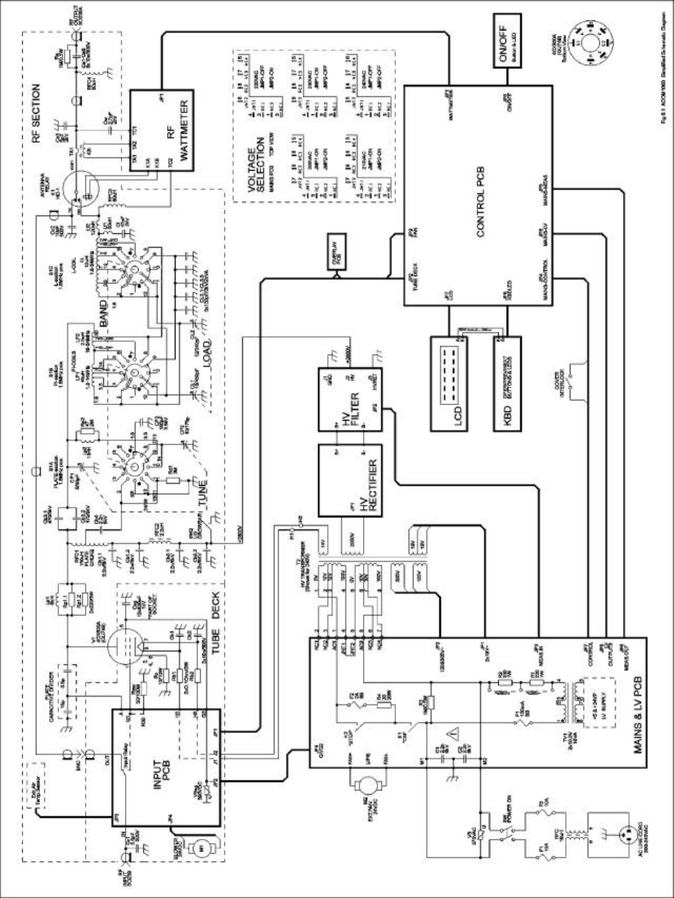
Exhibit 8 14 —17
6-4. The ACOM1000 Simplified Schematic Diagram
See Fig.6-1 ACOM1000 Simplified Schematic Diagram. * The 4CX800A (GU74B) Svetlana high performance ceramic-metal tetrode (V1) with plate
dissipation of 800W is grid-driven. The input signal from the RF INPUT jack is passed through a broadband input matching circuit, which comprises
Exhibit 8 15 —17
some components in the INPUT PCB and Rsw. This circuit tunes out the input capacitance of the tube. The swamping resistor Rsw is a termination
load for this circuit and can dissipate up to 100W of RF drive power.
Cathode resistor Rc creates DC and RF negative feedback, thus stabilizing the gain and equalizing the frequency response. The varistor VSsg in the
screen grid circuit protects the tube screen grid, and voltage regulator in the events of a flashover.
The combination Lp1-Rp1 in the plate circuit is a VHF/UHF parasitic suppressor. DC plate voltage is fed through chokes RFC1-RFC2 and the
capacitor Cb3 blocks it from the output. The output circuit comprises LP1, LP2, LL, CP1-CP3, and CL1-CL3 which form a classic Pi-L network and
suppress the harmonic frequency emissions. This tank is switched and tuned over the bands by S1A-S1C and the air variable capacitors CP1, 2 and
CL1, 2. The output signal is fed through an additional VHF low-pass filter for frequencies above 55MHz (Lf1, Lf2 and Cf). Then it is passed through the
vacuum antenna relay K1, wattmeter current transformer TA1, and a high-pass filter RFC4-Ca for frequencies below 100kHz, to the antenna output.
The chokes RFC3 and RFC4 keep track of the antenna relay contact conditions and together with Ca prevent the plate supply from reaching the
antenna. RFC4 shunts it to ground if the DC blocking capacitor Cb3 fails. The resistor Ra protects the amplifier from charging Electro-static energy fed
by the antenna.
The PLATE CAPACITIVE DIVIDER and RF WATTMETER are the main sources of information for the control circuit of the amplifier during the antenna
impedance matching process. The control circuit is based on the 80C552 micro-controller from Philips.
All voltages are delivered from the MAINS&LOW VOLTAGE and HIGH VOLTAGE SUPPLY PCBs. The control grid, screen grid and plate currents,
plate cooling airflow temperature, reflected power etc. are permanently monitored. Many software-derived protections are based on this information.
* Detailed electrical schematic diagrams are available from ACOM or from your dealer on request.
6-5. Troubleshooting
See S.5-3 for the method of reading the auto-protection signatures. You can decode them using the information below. *
The signatures are structured in two lines, three groups by six symbols for every one event of auto-protection. The last event is numbered as 1A-1B
pair of lines, and the oldest one is 7A-7B.
The meaning of the first group is as follows:
a) nA — the number of the trip;
b) Next three symbols mean the following:
PN0 — tests made during Power-On procedure, before HV is ON;
PN2 — tests made during Power-On procedure, after HV is ON and 1 second after step-start is closed;
SB0 — tests made in Stand-By, during the warm-up period or while entering Stand By (from Operate);
SB2 — tests made during Stand-By, after the warm-up period;
PR0 — tests made while entering Operate;
PR2 — tests made during Operate;
TR0 — antenna relay tests made while changing from Tx to Rx (during Operate)
TR2 — antenna relay tests made while changing from Rx to Tx (during Operate)
TR4 — antenna relay tests made during Tx (Operate mode)
TR6 — antenna relay tests made during Rx (Operate mode)
c) The last symbol of the first group designates the kind of the input parameter, which caused the protection to trip. The abbreviations in brackets
below are the signal names/designations according to the CONTROL PCB electrical schematic diagram and signal type:
1 — peak forward power (pfwd, analogue)
2 — reflected power (rfl, analogue)
3 — input (drive) power (inp, analogue)
4 — peak anode alternate voltage (paav, analogue)
5 — screen grid current (g2c, analogue)
6 — plate current (ipm, analogue)
7 — high voltage (hvm, analogue)
8 — exhaust air temperature (temp, analogue)
9 — drive power exists (*GRIDRF, logic)
A — antenna power exists (*PANT, logic)
B — output relay closed (ORC, logic)
C — arc fault (ARCF, logic)
D — control grid current too high (G1C, logic)
E — +24VDC power supply error (PSE, logic)
F — low airflow (LAIR, logic)
For instance, «1ATR4B» in first group would mean that the last auto-protection (1A) tripped by the antenna relay tests made during Tx — Operate mode
(TR4), and the «output relay closed — ORC» signal was failing (B).
The next five groups of symbols carry information about the analogue and logic values as measured by the micro-controller (at the moment of auto-
protection trip).
* Additional information is available from ACOM or from your dealer on how to interpret these values. Using an EXCEL APPLICATION (available from
ACOM or your dealer free of charge) and a PC, you can decode these signatures easily by yourself.
In case it is necessary to ship the amplifier please see S.7-3.
7. SPECIFICATIONS
7-1. Parameters
a) Frequency Coverage: All amateur bands 1.8-54MHz, extensions and/or changes on request.
b) Power Output: 1000W PEP or continuous carrier, no mode limit.
In continuous carrier modes (RTTY etc.) for transmissions longer than 15 minutes (up to several hours depending on
ambient temperature), the external auxiliary fan must be mounted.
c) Intermodulation Distortion: Better than 35dB below rated output.
d) Hum and noise: Better than 40dB below rated output.
Exhibit 8 16 —17
e) Harmonic Output Suppression:
1.8-29.7MHz — better than 50dB below rated output,
50-54MHz — better than 66dB below rated output.
f) Input and Output Impedances:
— Nominal value: 50 Ohm unbalanced, UHF (SO239) type connectors;
— Input circuit: broadband, VSWR less than 1.3:1, 1.8-54MHz continuously (no tunings, no switching);
— Bypass path VSWR less than 1.1:1, 1.8-54MHz continuously;
— Output (antenna) impedance matching capability: VSWR up to 3:1 or higher.
g) RF Gain: 12.5dB typically, frequency response less than 1dB (50 to 60W drive power for rated output).
h) Primary Power: 170-264V (200, 210, 220, 230 & 240V nominal taps (100, 110 & 120V taps on request), +10% -15%
tol.), 50-60Hz, single phase, 2200VA consumption at rated output.
i) Complies with CE safety and electromagnetic compatibility requirements as well as FCC-regulations (10 & 12m bands
lock provided).
l) Size & Weight (operating): W422mm x D355mm x H182mm, 18kg.
m) Operating environments:
— Temperature range: 0…+50 degs. Celsius;
— Humidity: up to 75% @ +35 degs. Celsius.
— Height: up to 3000m above sea level without output deterioration.
7-2. Functions
a) Antenna Impedance Matching Process: plate-load True Resistance Indicator (TRI) aided.
b) T/R System: QSK operation with built-in, vacuum RF antenna relay (special quiet installation).
c) Protections:
— Cover interlock for operator’s safety;
— Inrush power-on current control;
— High voltage, control grid, screen grid, and plate currents;
— Exhaust air temperature;
— T/R sequencing;
— Antenna relay contacts, including RF power induced in antenna from another nearby transmitter;
— Antenna matching quality;
— Reflected power;
— RF arcs, including in antenna system;
— Overdrive.
d) Signatures of the amplifier internal status are stored in a nonvolatile memory for the seven most recent auto
protection trips.
e) Dot matrix backlighted alphanumeric LCD with bargraph for forward peak power and text messages to the operator.
f) Measurement and constantly monitoring of 12 most important parameters of the amplifier via LCD.
g) Menu-selectable LCD Backlight and Contrast.
h) Tube: a single 4CX800A (GU74B) high-performance ceramic-metal tetrode of Svetlana with plate dissipation of
800W, grid driven, forced air-cooling.
7-3. Storage and Shipment
C A U T I O N
Should you need to transport the amplifier, use the original packing as described below.
First, switch off the amplifier. Pull the mains plug out of the outlet. Disconnect all cables from the rear panel of the
amplifier (remove the ground connection the last). Finally, pack the amplifier in its original carton.
a) Storage environments: the amplifier can be kept packed in dry and ventilated unheated premises without chemically
active substances (acids, alkalis etc.) in the following climatic environment:
— Temperature range: -40 to +70 degs. Celsius;
— Humidity: up to 75% @ +35 degs. Celsius.
b) Shipping Size and Weight:
W590mm x D430mm x H305mm, 20kg.
c) Shipping environments: all types of transportation, including aircraft baggage section up to 12000 meters above sea
level.