POST
Description
(hex)
8.1.
Start power on sequence
8.2.
Enable ATX power supply
8.3.
ATX power supply ready
8.4.
DDR voltage ready
8.5.
Setup PWM for CPU core voltage
8.6.
Assert PWM for CPU core voltage
8.7.
Check CPU core voltage
8.8.
CPU core voltage ready
8.9.
Initial clock generator IC
8.A.
North Bridge chipset voltage ready
8.B.
AGP voltage ready
8.C.
3VDUAL voltage ready
8.D.
VDDA 2.5V voltage ready
8.D.
GMCHVTT voltage ready
8.E.
Check CPU fan speed
8.F.
Assert all power ready
Complete µGuru initial process
9.0.
AWARDBIOS take over booting job
9.1.
Start power off sequence
9.2.
De-Assert all power
9.3.
De-Assert power on
9.4.
De-Assert LDT Bus power
9.5.
De-Assert PWM for CPU core voltage
9.6.
De-Assert CPU core voltage
9.7.
Check CPU core voltage
9.8.
De-Assert ATX power supply
9.9.
Complete power off sequence
Either the external «EZ-CCMOS1» switch or the internal «CCMOS1» jumper is not
C.C.
set to its normal position.
F.0.
Button reset
F.1.
SoftMenu reset
F.2.
Power on sequence timeout
F.3.
Power off sequence timeout
5-4
Power On Sequence
Power Off Sequence
Others
IP35 Pro
Куратор(ы):
Focusnik
| Автор | Сообщение | |||
|---|---|---|---|---|
|
||||
|
Куратор темы Статус: Не в сети |
Обсуждение материнских плат Abit IP35-series — Вопросы, обсуждавшиеся в FAQ’е будут удаляться. Цитата: Запрещается: Зеркало официальной страницы abit с архивами прошивок Альтернативные источники для загрузки прошивок, включающие прошивки с поддержкой Е0/R0 степпинга: бэта-версии биосов для iP35 Pro можно взять >>здесь<< Тема по модификации прошивок BIOS для поддержки процессоров в конструктиве LGA771 Сначала читаем >>FAQ<< — потом уже спрашиваем здесь! Отредактировано куратором: Darth Vader. Дата: 25.05.2009 21:59 Последний раз редактировалось Focusnik 12.02.2017 21:36, всего редактировалось 5 раз(а). |
| Реклама | |
|
Партнер |
|
coolpix112 |
|
|
Junior Статус: Не в сети |
Всем доброго времени суток. 83 это «save all data in stack back to CMOS» Жалко мамку, верой и правдой служила больше 10 лет(((((((((( |
|
guf4eggg |
|
|
Junior Статус: Не в сети |
Подскажите пожалуйста где в BIOS отключить питание на USB при выключенном питании… Плата IP35 |
|
Focusnik |
|
|
Куратор темы Статус: Не в сети |
На сколько я помню — нигде. Можно попробовать выключить поддержку в BIOS USB клавиатуры и мыши. Но не факт, что поможет и потом в BIOS можно будет попасть только с PS/2 клавиатуры. |
|
Leno |
|
|
Junior Статус: Не в сети |
Столкнулся с тем что IP 35 PRO не стартует с кодом 9.0 если в первый слот поставить GTX 560 Ti, если переставить во второй товсе прекрасно грузится но работает на скорости 4х. Гугление не спасло есть темы с похожими проблемами но там пк не грузится совсем. |
|
Donavan |
|
|
Junior Статус: Не в сети |
Поделюсь своим опытом установки Xeon E5450 в Abit ip35 Pro. TL;DR: Xeon E5450 у меня заработал в Abit ip35 Pro только на 14 версии биоса, куда я сам добавил микрокоды. Дано: Преамбула:
Рисковать суммой в 3 т.р. не хотелось, а цена риска топового Core 2 Duo E8600 выглядела вполне приемлемой. Позже я узнал о варианте установки Xeon’ов в S775 сокет, и что можно с Aliexpress за ~1200 руб. заказать улучшенный аналог топового Quad Q9650 и не смог удержаться. Реализация: Тут я уже решил пробовать патчить сам по мануалу, брал также биосы из пака Ligushka, только накатывал на них «Desktop LGA 771 and LGA 775 microcode». 8. 18ZZZ + E0 — всё тоже самое; Здесь я уже практически уверился, что зря я рискнул и заказал степпинг E0, в погоне за разгоном, что надо было брать C0 и без проблем пользоваться (читал в этой ветке, что с более старым степпингом у нас нет проблем…). Ну, на последок, решил попробовать прошить 14 биос, который без поддержки 45 нм и на нём даже E8600 не завёлся, что уж думать о E5450… 11. 14ZZZ + E0 — Всё заработало!!! Двойной старт ещё не тестил, но вроде его нет. Уходит в сон и просыпается как надо, вроде даже не отваливается виртуализация VT-x при этом. Настройки в биосе сохраняются (разогнал по шине до 3.51 GHz, дальше IntelBurnTest начинает выдавать сбои в тестах и винда виснет). Правда температура по процу фантастическая, порядка 20 градусов в биосе, но в прогах по ядрам показывает адекватно. В заключение:
P.S.: Если вы задаётесь вопросом «Стоит ли оно того?», вот мой бенчмарк из CPU-Z |
|
DmitryZzz |
|
|
Member Статус: Не в сети |
Donavan писал(а): Поделюсь своим опытом установки Xeon E5450 в Abit ip35 Pro. читал ранее подобное, долго думал. https://valid.x86.fr/5qqfb3 это со всей тряхомудией типа клауд-клиентов, антивирусов и прочих торрентов на 5-летней винде, на чистой могло быть больше. |
|
Donavan |
|
|
Junior Статус: Не в сети |
DmitryZzz, видел твои сообщения, про борьбу с BSOD, которые, вероятно, решились обновлением прошивки SSD. Просто я как раз решил докупить SSD какой-нибудь на 120 Гб под систему и на этом вопрос с ПК закрыть на несколько лет. А теперь может получиться, что у меня на 14-ой прошивки могут быть проблемы? Но моя прошивка ZZZ-модифицированная, плюс с обновлением от Ligushka: Хочу понять ситуацию, вероятность и масштаб проблем с SSD. |
|
Alexey B |
|
|
Member Статус: Не в сети |
DmitryZzz Donavan Собрал тут с месяц назад пару систем на 771-ом проциках: 5440 и 5450. |
|
Donavan |
|
||
|
Junior Статус: Не в сети |
Donavan, Alexey B, а ещё такой вопрос. Сам драйвер обновлял, откатывал на более старые версии; в настройках ставил «Предпочтительный режим макс. производительности»; в реестре поставил задержку отрубания TdrDelay в 10 секунд — не помогло. У вас не было подобных проблем с вылетом драйвера под видеокарту на этой матери?
|

|
caligula73 |
|
|
Member Статус: Не в сети |
Donavan пробуйте установить старый драйвер с диска который шел в комплекте с GeForce 8600 GT Palit Sonic+ |
|
DmitryZzz |
|
|
Member Статус: Не в сети |
Donavan писал(а): DmitryZzz, видел твои сообщения, про борьбу с BSOD, которые, вероятно, решились обновлением прошивки SSD. почитай всю мою историю 16 года Abit IP35-series на Intel® P35 Express [+FAQ] там не я, а juk_777 писал(а): DmitryZzz пёс его знает, в чем именно проблема была. но факт все заработало после апгрейда проши ССД. Добавлено спустя 7 минут 21 секунду: Alexey B писал(а): В общем 771-ые понравились больше: меньше греются, имеют достойную производительность и вообще не спорю, у них базовая частота 2,8 и 3 против 2,4 у q6600. и тепловой пакет 80 ватт против 105 у квада. 45nm против 65nm решает. |
|
Alexey B |
|
|
Member Статус: Не в сети |
Donavan Предполагаю, что что-то с самой картой… |
|
Donavan |
|
|
Junior Статус: Не в сети |
caligula73, ок, попробую, спасибо. |
|
Donavan |
|
|
Junior Статус: Не в сети |
Подключил A-DATA Ultimate SU650 ASU650SS-120GT-C, заработал без проблем, уже установил на него High Sierra. CrystalDiskMark 6 Sequential Read (Q= 32,T= 1) : 285.791 MB/s Test : 1024 MiB [Z: 0.1% (0.1/111.7 GiB)] (x5) [Interval=5 sec] |
 : 109.988 MB/s [ 26852.5 IOPS]
|
MicroHCR |
|
|
Member Статус: Не в сети |
Больше двух лет пашет Самсунг 750эво на Абит IP35 с биос 13 мод без проблем, все летает. Стоит Xeon 5450 С0 и 8 Гб ОЗУ, разгонял проц до 4 ГГц без особых усилий. Биос температуру немного занижает, двойного старта нет, в простое частота падает как положено, все вообще ок). |
|
aggro |
|
|
Junior Статус: Не в сети |
Всем привет. Материнка IP35-E, решил поставить к своему харду ссд от кингстон. Поставил ссд, установил на него винду чистую но теперь хдд перестал работать. в биосе выставил конечно старт с ссд а хард хотел оставить суто под файлы. запустил комп и хард просто начал издавать щелчки. иногда в системе отображается он он щелкает и работает медленно очень, иногда отваливается , а в биосе постоянно отображается . не знаю в чем может быть проблема, потому что сам ссд работает прекрасно |
|
JohnnyD |
|
||
|
Junior Статус: Не в сети |
всем привет! подскажите знающие,мать abit ip35pro процессор xeon e5420 стоит мод биос 14(от Donavan) но процессор заводится на частоте 2389,вместо положенной 2.500мгц..НО , 2 ядра работают на 2.500 а другие 2 на 2.389мгц!!множитель давольно разный(у первый двух ядер максимальный 7) а у следующих двух ( 7.5) в биосе максимальный множитель 7 стоит,7.5 нет . но в системе показывает что 2 из 4 работают с повышенным множителем .. Вложение:
|
 прикладываю скрин,возможно я не силен в описании,но суть проблемы изложил как мог.надеюсь на вашу помощь.
|
JohnnyD |
|
||
|
Junior Статус: Не в сети |
Donavan писал(а): Поделюсь своим опытом установки Xeon E5450 в Abit ip35 Pro. а множитель какой у тебя максимальный стоит? у меня на твоём биосе максимум 7 .. а должно быть 7.5 .. все делал по инструкции но увы.
|
|
Vibesan |
|
|
Junior Статус: Не в сети |
Ребята, вопрос такой. Дружит ли ip 35 e c пониженным множителем fsb:dram ? x5450 на данном сабже смог разогнать с четырьмя плашками kingston pc6400 только до 3.4 ггц, память работает стабильно на 920 мгц. Питальник tk lite power 750w, охлад thermaltake bt |
—
| Вы не можете начинать темы Вы не можете отвечать на сообщения Вы не можете редактировать свои сообщения Вы не можете удалять свои сообщения Вы не можете добавлять вложения |
Лаборатория
Новости
POST
Description
(hex)
8.1.
Start power on sequence
8.2.
Enable ATX power supply
8.3.
ATX power supply ready
8.4.
DDR voltage ready
8.5.
Setup PWM for CPU core voltage
8.6.
Assert PWM for CPU core voltage
8.7.
Check CPU core voltage
8.8.
CPU core voltage ready
8.9.
Initial clock generator IC
8.A.
North Bridge chipset voltage ready
8.B.
AGP voltage ready
8.C.
3VDUAL voltage ready
8.D.
VDDA 2.5V voltage ready
8.D.
GMCHVTT voltage ready
8.E.
Check CPU fan speed
8.F.
Assert all power ready
Complete µGuru initial process
9.0.
AWARDBIOS take over booting job
9.1.
Start power off sequence
9.2.
De-Assert all power
9.3.
De-Assert power on
9.4.
De-Assert LDT Bus power
9.5.
De-Assert PWM for CPU core voltage
9.6.
De-Assert CPU core voltage
9.7.
Check CPU core voltage
9.8.
De-Assert ATX power supply
9.9.
Complete power off sequence
Either the external «EZ-CCMOS1» switch or the internal «CCMOS1» jumper is not
C.C.
set to its normal position.
F.0.
Button reset
F.1.
SoftMenu reset
F.2.
Power on sequence timeout
F.3.
Power off sequence timeout
5-4
Power On Sequence
Power Off Sequence
Others
IP35 Pro
Куратор(ы):
Focusnik
| Автор | Сообщение | |||
|---|---|---|---|---|
|
||||
|
Куратор темы Статус: Не в сети |
Обсуждение материнских плат Abit IP35-series — Вопросы, обсуждавшиеся в FAQ’е будут удаляться. Цитата: Запрещается: Зеркало официальной страницы abit с архивами прошивок Альтернативные источники для загрузки прошивок, включающие прошивки с поддержкой Е0/R0 степпинга: бэта-версии биосов для iP35 Pro можно взять >>здесь<< Тема по модификации прошивок BIOS для поддержки процессоров в конструктиве LGA771 Сначала читаем >>FAQ<< — потом уже спрашиваем здесь! Отредактировано куратором: Darth Vader. Дата: 25.05.2009 21:59 Последний раз редактировалось Focusnik 12.02.2017 21:36, всего редактировалось 5 раз(а). |
| Реклама | |
|
Партнер |
|
coolpix112 |
|
|
Junior Статус: Не в сети |
Всем доброго времени суток. 83 это «save all data in stack back to CMOS» Жалко мамку, верой и правдой служила больше 10 лет(((((((((( |
|
guf4eggg |
|
|
Junior Статус: Не в сети |
Подскажите пожалуйста где в BIOS отключить питание на USB при выключенном питании… Плата IP35 |
|
Focusnik |
|
|
Куратор темы Статус: Не в сети |
На сколько я помню — нигде. Можно попробовать выключить поддержку в BIOS USB клавиатуры и мыши. Но не факт, что поможет и потом в BIOS можно будет попасть только с PS/2 клавиатуры. |
|
Leno |
|
|
Junior Статус: Не в сети |
Столкнулся с тем что IP 35 PRO не стартует с кодом 9.0 если в первый слот поставить GTX 560 Ti, если переставить во второй товсе прекрасно грузится но работает на скорости 4х. Гугление не спасло есть темы с похожими проблемами но там пк не грузится совсем. |
|
Donavan |
|
|
Junior Статус: Не в сети |
Поделюсь своим опытом установки Xeon E5450 в Abit ip35 Pro. TL;DR: Xeon E5450 у меня заработал в Abit ip35 Pro только на 14 версии биоса, куда я сам добавил микрокоды. Дано: Преамбула:
Рисковать суммой в 3 т.р. не хотелось, а цена риска топового Core 2 Duo E8600 выглядела вполне приемлемой. Позже я узнал о варианте установки Xeon’ов в S775 сокет, и что можно с Aliexpress за ~1200 руб. заказать улучшенный аналог топового Quad Q9650 и не смог удержаться. Реализация: Тут я уже решил пробовать патчить сам по мануалу, брал также биосы из пака Ligushka, только накатывал на них «Desktop LGA 771 and LGA 775 microcode». 8. 18ZZZ + E0 — всё тоже самое; Здесь я уже практически уверился, что зря я рискнул и заказал степпинг E0, в погоне за разгоном, что надо было брать C0 и без проблем пользоваться (читал в этой ветке, что с более старым степпингом у нас нет проблем…). Ну, на последок, решил попробовать прошить 14 биос, который без поддержки 45 нм и на нём даже E8600 не завёлся, что уж думать о E5450… 11. 14ZZZ + E0 — Всё заработало!!! Двойной старт ещё не тестил, но вроде его нет. Уходит в сон и просыпается как надо, вроде даже не отваливается виртуализация VT-x при этом. Настройки в биосе сохраняются (разогнал по шине до 3.51 GHz, дальше IntelBurnTest начинает выдавать сбои в тестах и винда виснет). Правда температура по процу фантастическая, порядка 20 градусов в биосе, но в прогах по ядрам показывает адекватно. В заключение:
P.S.: Если вы задаётесь вопросом «Стоит ли оно того?», вот мой бенчмарк из CPU-Z |
|
DmitryZzz |
|
|
Member Статус: Не в сети |
Donavan писал(а): Поделюсь своим опытом установки Xeon E5450 в Abit ip35 Pro. читал ранее подобное, долго думал. https://valid.x86.fr/5qqfb3 это со всей тряхомудией типа клауд-клиентов, антивирусов и прочих торрентов на 5-летней винде, на чистой могло быть больше. |
|
Donavan |
|
|
Junior Статус: Не в сети |
DmitryZzz, видел твои сообщения, про борьбу с BSOD, которые, вероятно, решились обновлением прошивки SSD. Просто я как раз решил докупить SSD какой-нибудь на 120 Гб под систему и на этом вопрос с ПК закрыть на несколько лет. А теперь может получиться, что у меня на 14-ой прошивки могут быть проблемы? Но моя прошивка ZZZ-модифицированная, плюс с обновлением от Ligushka: Хочу понять ситуацию, вероятность и масштаб проблем с SSD. |
|
Alexey B |
|
|
Member Статус: Не в сети |
DmitryZzz Donavan Собрал тут с месяц назад пару систем на 771-ом проциках: 5440 и 5450. |
|
Donavan |
|
||
|
Junior Статус: Не в сети |
Donavan, Alexey B, а ещё такой вопрос. Сам драйвер обновлял, откатывал на более старые версии; в настройках ставил «Предпочтительный режим макс. производительности»; в реестре поставил задержку отрубания TdrDelay в 10 секунд — не помогло. У вас не было подобных проблем с вылетом драйвера под видеокарту на этой матери?
|
|
caligula73 |
|
|
Member Статус: Не в сети |
Donavan пробуйте установить старый драйвер с диска который шел в комплекте с GeForce 8600 GT Palit Sonic+ |
|
DmitryZzz |
|
|
Member Статус: Не в сети |
Donavan писал(а): DmitryZzz, видел твои сообщения, про борьбу с BSOD, которые, вероятно, решились обновлением прошивки SSD. почитай всю мою историю 16 года Abit IP35-series на Intel® P35 Express [+FAQ] там не я, а juk_777 писал(а): DmitryZzz пёс его знает, в чем именно проблема была. но факт все заработало после апгрейда проши ССД. Добавлено спустя 7 минут 21 секунду: Alexey B писал(а): В общем 771-ые понравились больше: меньше греются, имеют достойную производительность и вообще не спорю, у них базовая частота 2,8 и 3 против 2,4 у q6600. и тепловой пакет 80 ватт против 105 у квада. 45nm против 65nm решает. |
|
Alexey B |
|
|
Member Статус: Не в сети |
Donavan Предполагаю, что что-то с самой картой… |
|
Donavan |
|
|
Junior Статус: Не в сети |
caligula73, ок, попробую, спасибо. |
|
Donavan |
|
|
Junior Статус: Не в сети |
Подключил A-DATA Ultimate SU650 ASU650SS-120GT-C, заработал без проблем, уже установил на него High Sierra. CrystalDiskMark 6 Sequential Read (Q= 32,T= 1) : 285.791 MB/s Test : 1024 MiB [Z: 0.1% (0.1/111.7 GiB)] (x5) [Interval=5 sec] |
 : 109.988 MB/s [ 26852.5 IOPS]
|
MicroHCR |
|
|
Member Статус: Не в сети |
Больше двух лет пашет Самсунг 750эво на Абит IP35 с биос 13 мод без проблем, все летает. Стоит Xeon 5450 С0 и 8 Гб ОЗУ, разгонял проц до 4 ГГц без особых усилий. Биос температуру немного занижает, двойного старта нет, в простое частота падает как положено, все вообще ок). |
|
aggro |
|
|
Junior Статус: Не в сети |
Всем привет. Материнка IP35-E, решил поставить к своему харду ссд от кингстон. Поставил ссд, установил на него винду чистую но теперь хдд перестал работать. в биосе выставил конечно старт с ссд а хард хотел оставить суто под файлы. запустил комп и хард просто начал издавать щелчки. иногда в системе отображается он он щелкает и работает медленно очень, иногда отваливается , а в биосе постоянно отображается . не знаю в чем может быть проблема, потому что сам ссд работает прекрасно |
|
JohnnyD |
|
||
|
Junior Статус: Не в сети |
всем привет! подскажите знающие,мать abit ip35pro процессор xeon e5420 стоит мод биос 14(от Donavan) но процессор заводится на частоте 2389,вместо положенной 2.500мгц..НО , 2 ядра работают на 2.500 а другие 2 на 2.389мгц!!множитель давольно разный(у первый двух ядер максимальный 7) а у следующих двух ( 7.5) в биосе максимальный множитель 7 стоит,7.5 нет . но в системе показывает что 2 из 4 работают с повышенным множителем .. Вложение:
|
|
JohnnyD |
|
||
|
Junior Статус: Не в сети |
Donavan писал(а): Поделюсь своим опытом установки Xeon E5450 в Abit ip35 Pro. а множитель какой у тебя максимальный стоит? у меня на твоём биосе максимум 7 .. а должно быть 7.5 .. все делал по инструкции но увы.
|
|
Vibesan |
|
|
Junior Статус: Не в сети |
Ребята, вопрос такой. Дружит ли ip 35 e c пониженным множителем fsb:dram ? x5450 на данном сабже смог разогнать с четырьмя плашками kingston pc6400 только до 3.4 ггц, память работает стабильно на 920 мгц. Питальник tk lite power 750w, охлад thermaltake bt |
—
| Вы не можете начинать темы Вы не можете отвечать на сообщения Вы не можете редактировать свои сообщения Вы не можете удалять свои сообщения Вы не можете добавлять вложения |
Лаборатория
Новости
-
alexandrpro2
Junior
Материнка успешно статует, издает один короткий пик и виснет на лого материнки. Пост карты нет. Визуально на материнке все целое. Процессоры перепробывал разные. Биосы перешивал несколько раз, разных версий. Ничто болезнь эту не лечит.
Может кто с таким сталкивался, подскажет куда копать.
-
rs
Junior
Повідомлення
10.11.2015 10:21
во-первых поменьше шейте разных биосов) во-вторых посмотрите нет ли на плате перемычек запрещающих прошивку биос…
а для начала просто осмотрите плату на предмет вздувшихся конденсаторов, коротких замыканий (или залипших контактов) в слотах, разъемах и пр. может где-то в цепях питания ухудшилось качество спайки…
один короткий писк — это хорошо) но попробуйте другую память иили, если потребуется, протрите контакты памяти ластиком иили спиртом. удачи!
кстати к зависаниям могут приводить и вздувшиеся кондеры в самом блоке питания…
-
ПрихлопБилл
Member

- Звідки: hell on Earth

Повідомлення
10.11.2015 10:31
alexandrpro2:Материнка успешно статует, издает один короткий пик и виснет на лого материнки. Пост карты нет. Визуально на материнке все целое. Процессоры перепробывал разные. Биосы перешивал несколько раз, разных версий. Ничто болезнь эту не лечит.
Может кто с таким сталкивался, подскажет куда копать.
Успешно стартует — это когда выходит на поиски загрузочного устройства. Копать к ремонтникам.
-
DEVES
Member

- Звідки: Україна

Повідомлення
10.11.2015 11:03
Насколько я помню, эта маман не очень дружила с памятью на микронах.
Конкретно моя IP35 Pro не хотела работать с такими планками


P.S. ну и не забываем смотреть на индикатор POST кодов…
-
alexandrpro2
Junior
Повідомлення
10.11.2015 16:27
Заказал себе пост карту почтой. После получения крты проверю материнку о результатах посткодов отпишусь.
Звуковые сигналы AMI BIOS
Сигнал Значение
1 короткий Ошибок не обнаружено, загрузка системы продолжается
2 коротких Ошибка четности оперативной памяти
3 коротких Неисправность первых 64 Кбайт оперативной памяти
4 коротких Неисправен системный таймер
5 коротких Неисправность процессора
ну и т.д.
-
alexandrpro2
Junior
Повідомлення
20.11.2015 19:08
При запуске с установленной Post картой видно, что мать на какое то время задумывается на пост коде 50 и виснет на коде 52 (Award bios). Есть обоснованные подозрения, что на этом коде идет обращение к юэсби портам.
Обратил внимание, что греется юг. Один внутренний юэсби разъем со сгоревшим предохранителем по линии 5 V. Видать и в прям к ремонтникам.
-
46Tolik
Member
Повідомлення
20.11.2015 22:31
ПрихлопБилл:
alexandrpro2:Материнка успешно статует, издает один короткий пик и виснет на лого материнки. Пост карты нет. Визуально на материнке все целое. Процессоры перепробывал разные. Биосы перешивал несколько раз, разных версий. Ничто болезнь эту не лечит.
Может кто с таким сталкивался, подскажет куда копать.Успешно стартует — это когда выходит на поиски загрузочного устройства. Копать к ремонтникам.
не нужно людей вводить в заблуждение. изучи мат часть что означает нет старта ![]()
-
Mixx
Member
- Звідки: Чернигов

Повідомлення
20.01.2016 05:42
alexandrpro2
если подключена флешка — вытяньте, а вобще ето лечится отключением последней функции в настройках юсб в биосе, помогает перепрошивка биоса на ранние версии, там биос должен нормально грузить, если конечно не конец южнику, что тоже возможно, пробуйте ![]()
Не путать с «обычными» POST-кодами! Это ошибки, выдаваемые чипсетом (а не процессором) до того, как, собственно, процессор стартует (выполняет первую команду). На платах от Abit подобная технология называется µGuru. Для отличия «обычных» POST-кодов от «гурушных» — последние помечаются точками. Т.е. POST-код: 90, а mGuru-код: 9.0.
Контроллер Espada PCI SATA Sil 3512 и DVD-RW не загружается компьютер
Возникла следующая проблема. Решил купить привод SATA и контроллер PCI SATA Espada Sil3512, установил все , подключил и компьютер не загрузился, при отключении привода от контроллера комп попытался загрузиться, но оказалось что винде капут, пришлось переустанавливать. Что я делаю не правильно и в чем может быть проблема?
Abit AN8 32X cmos checksum error
Здравствуйте господа форумчане. Проблема в следующем, при включении компа на встроенном пост индикаторе материнки сразу показывает 9.0., после обнуления CMOS мать стартует проходит пост и останавливается на сообщении cmos chcksum error нажмите F1 или Del…, если нажать F1 то винда грузится и все норм до перезагрузки, но если зайти в Bios, после выхода из него комп не грузится и пост индикатор показывает F.1..В мануале Abit код 9.0. расшифровывается как «Complete uGuru initial process AWARD bios take over booting job», а F.1. как «SoftMenu reset».
Abit AN9 32X Fatality — не запускается с мощными видеокартами
Мать запускается с видяхой HD2400PR и без проблем работает, но если вставить GF8800GTS или др. более мощную, то мать не стартует. uGuru показывает код 9.0. После ресета, POST = С1. Проверил питание PCI-e, 12v и 3,3v в норме, но вот PWRGD на PCI-e прыгает с частотой 2 герца из лог.1 в 0.
Питание 3.3v собрано на Winbond W83303AG. Но вот откуда идет сигнал PWRGD не могу понять? С северного моста может быть? Подскажите, куда рыть
Кстати, если видяху вставлять в другой PCI-e слот, то мать останавливается на POST = 5d и PWRGD в норме.
Мать ABIT IP35 PRO ревизия 1.1 не стартует. Камень Р04 2,88/1М/800. Память Кингстон KVR800В2Т5/512. Камень, мать, бп проверены.
Интересное поведение ABIT AN8
Доброго времени суток, господа форумчане. Года полтора назад мой друг купил себе плату ABIT AN8 (предел мечтаний на то время). Изначально носил её к местным шаманам которые, судя по всему, шаманили над микросхемкой U33 с «грозной» надписью ABIT AC2001a (судя по найденому в сети — она чтото мониторит) и сместили её при монтаже.
Запускается со сбоями.
Помогите справиться с проблемой!!!
Система: MB ABIT AN7 mGuru 400 Ultra nForce2; CPU AMD Athlon XP 2500+; video Radeon 9600 Pro; RAM 2×256 PC 3200
POST 9F на Abit AV8 и потом полет нормальный
Имеется мать Abit AV8 с BIOS 2.8 версии и с Athlon64 3000+ venice на борту. И проблема с ней, возникшая несколько дней назад: при нажатии на кнопку питания материнка запускается, на встроенной POST-карте цифири меняются, но через пару секунд сам выключается, а на индикаторе горит 9F. После нового запуска всё в норме, но высвечивается сообщение «System is running in Fail-Safe State. Please recheck BIOS CMOS SETUP».
 Loading…
![]()
IP35 Pro
Motherboard
Socket 775
User’s Manual
About this Manual:
This user’s manual contains all the information you may need for setting up this motherboard. To read the user’s manual of PDF format (readable by Adobe Reader), place the “Driver & Utility CD” into the CD-ROM drive in your system. The auto-run screen will appear, click the “Manual” tab to enter its submenu. If not, browse the root directory of the CD-ROM via the File Manager, and double click the “AUTORUN” file.
Intel P35 / ICH9R
FSB 1333 MHz
Dual Channel DDR2 800
Dual PCI-E X16 Slots
Dual Gigabit LAN
6x Internal, 2x External SATA
3Gb/s Connectors
USB 2.0 / IEEE 1394
7.1-Channel HD Audio
abit uGuru™ Technology
abit Silent OTES™ Technology
External CMOS Clearing
Switch
Quick Power & Reset Button
Vista Premium HW Ready
Appendix QIG Multilingual Utility & Driver Setup BIOS Setup Hardware

IP35 Pro
User’s Manual
English + Multilingual QIG
P/N: 4310-0000-89
Rev. 2.00, May 2007
Copyright and Warranty Notice
The information in this document is subject to change without notice and does not represent a commitment on part of the vendor, who assumes no liability or responsibility for any errors that may appear in this manual.
No warranty or representation, either expressed or implied, is made with respect to the quality, accuracy or fitness for any particular part of this document. In no event shall the manufacturer be liable for direct, indirect, special, incidental or consequential damages arising from any defect or error in this manual or product.
Product names appearing in this manual are for identification purpose only and trademarks and product names or brand names appearing in this document are the property of their respective owners.
This document contains materials protected under International Copyright Laws. All rights reserved. No part of this manual may be reproduced, transmitted or transcribed without the expressed written permission of the manufacturer and authors of this manual.
If you do not properly set the motherboard settings, causing the motherboard to malfunction or fail, we cannot guarantee any responsibility.
The Following Information is Only for EU-member States:
Directive 2002/96/EC on Waste Electrical and Electronic Equipment (WEEE): The use of the symbol indicates that this product may not be treated as household waste. By Ensuring this product is disposed of correctly, you will help prevent potential negative consequences for the environment and human health, which could otherwise be cause by inappropriate waste handling of this product. For more detailed information about recycling of this product, please contact your local city office, your household waste disposal service or the shop where you purchased the product.

Contents
|
1. Hardware Setup ……………………………………………………… |
1-1 |
|
|
1.1 |
Specifications……………………………………………………………………. |
1-1 |
|
1.2 |
Motherboard Layout …………………………………………………………… |
1-2 |
|
1.3 |
Choosing a Computer Chassis ………………………………………………. |
1-3 |
|
1.4 |
Installing Motherboard ……………………………………………………….. |
1-3 |
|
1.5 |
Checking Jumper Settings……………………………………………………. |
1-4 |
|
1.5.1 CMOS Memory Clearing Header and Backup Battery ………….. |
1-4 |
|
|
1.6 |
Connecting Chassis Components …………………………………………… |
1-6 |
|
1.6.1 Power Connectors ……………………………………………………… |
1-6 |
|
|
1.6.2 Front Panel Switches & Indicators Headers ……………………… |
1-7 |
|
|
1.6.3 FAN Power Connectors ……………………………………………….. |
1-7 |
|
|
1.7 |
Installing Hardware……………………………………………………………. |
1-8 |
|
1.7.1 CPU Socket 775…………………………………………………………. |
1-8 |
|
|
1.7.2 DDR2 Memory Slots………………………………………………….. |
1-10 |
|
|
1.7.3 PCI Express X16 Add-on Slots (Install Graphics Card) ………. |
1-11 |
|
|
1.8 |
Connecting Peripheral Devices ……………………………………………. |
1-12 |
|
1.8.1 Floppy and IDE Disk Drive Connectors ………………………….. |
1-12 |
|
|
1.8.2 Serial ATA Connectors ………………………………………………. |
1-13 |
|
|
1.8.3 Additional USB 2.0 Port Headers………………………………….. |
1-14 |
|
|
1.8.4 Additional IEEE 1394 Port Headers ………………………………. |
1-14 |
|
|
1.8.5 Internal Audio Connector …………………………………………… |
1-15 |
|
|
1.8.6 Front Panel Audio Connection Header …………………………… |
1-15 |
|
|
1.8.7 S/PDIF Output Connection Header……………………………….. |
1-17 |
|
|
1.8.8 PCI and PCI Express X1 Slots ……………………………………… |
1-17 |
|
|
1.8.9 Guru Panel Connection Header……………………………………. |
1-18 |
|
|
1.9 |
Onboard Indicators and Buttons………………………………………….. |
1-19 |
|
1.9.1 POST Code Displayer ………………………………………………… |
1-19 |
|
|
1.9.2 Power Source Indicators ……………………………………………. |
1-20 |
|
|
1.9.3 Onboard Buttons ……………………………………………………… |
1-20 |
|
|
1.10 Connecting Rear Panel I/O Devices ……………………………………. |
1-21 |
|
2. BIOS Setup…………………………………………………………….. |
2-1 |
|
|
2.1 |
μGuru™ Utility …………………………………………………………………… |
2-2 |
|
2.1.1 OC Guru ………………………………………………………………….. |
2-2 |
|
|
2.1.2 ABIT EQ…………………………………………………………………… |
2-4 |
|
|
2.2 |
Standard CMOS Features…………………………………………………… |
2-10 |
|
2.3 |
Advanced BIOS Features …………………………………………………… |
2-13 |
|
2.4 |
Advanced Chipset Features………………………………………………… |
2-16 |
|
2.5 |
Integrated Peripherals………………………………………………………. |
2-17 |
|
2.6 |
Power Management Setup …………………………………………………. |
2-21 |
|
2.7 |
PnP/PCI Configurations …………………………………………………….. |
2-23 |
|
2.8 |
Load Fail-Safe Defaults……………………………………………………… |
2-24 |
|
2.9 |
Load Optimized Defaults……………………………………………………. |
2-24 |
|
2.10 Set Password ………………………………………………………………… |
2-24 |
|
|
2.11 Save & Exit Setup…………………………………………………………… |
2-24 |
|
|
2.12 Exit Without Saving ………………………………………………………… |
2-24 |
|
|
IP35 Pro |
iii |
Appendix QIG Multilingual Utility & Driver Setup BIOS Setup Hardware
|
3. Driver & Utility ……………………………………………………….. |
3-1 |
|
|
3.1 |
CD-ROM AUTORUN ……………………………………………………………. |
3-1 |
|
3.2 |
Intel Chipset Software Installation Utility ………………………………… |
3-2 |
|
3.3 |
Intel Matrix Storage Manager……………………………………………….. |
3-2 |
|
3.4 |
Audio Driver …………………………………………………………………….. |
3-3 |
|
3.5 |
LAN Driver……………………………………………………………………….. |
3-4 |
|
3.6 |
JMicron SATA Driver…………………………………………………………… |
3-4 |
|
3.7 |
USB 2.0 Driver ………………………………………………………………….. |
3-4 |
|
3.8 abit μGuru ……………………………………………………………………….. |
3-5 |
|
|
3.9 |
SATA RAID Driver (for Windows Vista) …………………………………… |
3-6 |
|
3.10 SATA RAID Driver (for Windows XP, 2003, or 2000) ………………… |
3-6 |
|
4. Multilingual Quick Installation Guide ………………………… |
4-1 |
|
|
4.1 |
Français//Guide d’Installation Rapide……………………………………… |
4-1 |
|
4.2 |
Deutsch//Kurze Installationsanleitung…………………………………….. |
4-2 |
|
4.3 |
Italiano//Guida all’installazione rapida ……………………………………. |
4-3 |
|
4.4 |
Español//Guía rápida de instalación……………………………………….. |
4-4 |
|
4.5 |
Português//Guia de instalação rápida …………………………………….. |
4-5 |
|
4.6 |
Русский//Краткое руководство по установке ………………………… |
4-6 |
|
4.7 |
Eesti//Kiirpaigaldusjuhend …………………………………………………… |
4-7 |
|
4.8 |
Latviski//Ātrās instalēšanas instrukcija……………………………………. |
4-8 |
|
4.9 |
Lietuvių//Trumpas instaliavimo vadovas …………………………………. |
4-9 |
|
4.10 |
Polski//Instrukcja szybkiej instalacji……………………………………. |
4-10 |
|
4.11 |
Magyar//Gyorstelepítési útmutató………………………………………. |
4-11 |
|
4.12 |
Türkçe//Hızlı Kurulum Kılavuzu………………………………………….. |
4-12 |
|
4.13 اللغة العربية//دليل التركيب السريع………………….. |
4-13 |
|
|
4.14 |
فارسی// راﻩنمای نصب سریع……………………………………….. |
4-14 |
|
4.15 |
// ……………………………….. |
4-15 |
|
4.16 |
// ………………………………………………. |
4-16 |
|
4.17 |
Bahasa Malaysia//Panduan Pemasangan Ringkas ………………….. |
4-17 |
|
4.18 |
// ……………………………………………….. |
4-18 |
|
4.19 |
……………………………………………………………………… |
4-19 |
|
4.19.1 ……………………………………………………………………. |
4-19 |
|
|
4.19.2 ………………………………………………………… |
4-20 |
|
|
4.20 |
……………………………………………………………………… |
4-21 |
|
4.20.1 ……………………………………………………………………. |
4-21 |
|
|
4.20.2 ………………………………………………………… |
4-22 |
|
|
5. Appendix ……………………………………………………………….. |
5-1 |
|
|
5.1 POST Code Definitions………………………………………………………… |
5-1 |
|
|
5.1.1 AWARD POST Code Definitions……………………………………… |
5-1 |
|
|
5.1.2 AC2005 POST Code Definitions……………………………………… |
5-4 |
|
|
5.2 Troubleshooting (How to Get Technical Support?)…………………….. |
5-5 |
|
|
5.2.1 Q & A ……………………………………………………………………… |
5-5 |
|
|
5.2.2 Technical Support Form………………………………………………. |
5-8 |
|
|
5.2.3 Contact Information……………………………………………………. |
5-9 |
|
|
iv |
IP35 Pro |

1. Hardware Setup
1.1 Specifications
|
• 1x PCI-E X1 Slot |
||||
|
CPU |
||||
|
• |
3x PCI Slots |
|||
|
• LGA775 Socket for Intel processor of: |
||||
|
Core 2 Extreme Edition / Core 2 Quad / |
Internal I/O Connectors |
|||
|
Core 2 Duo, & |
• |
1x Floppy Port |
||
|
Pentium Extreme Edition / Pentium Dual |
||||
|
• 1x Ultra ATA 133 IDE Connector |
||||
|
Core / Pentium D / Pentium 4. |
||||
|
• 6x SATA 3Gb/s Connectors |
||||
|
• Supports FSB 1333MHz |
||||
|
• 4x USB 2.0 Headers |
||||
|
Chipset |
• |
2x IEEE 1394 Headers |
||
|
• Intel P35 / ICH9R |
• |
1x FP-Audio Header |
||
|
• 1x CD-In Connector |
||||
|
Memory |
||||
|
• 1x S/PDIF Out Header |
||||
|
• 4x 240-pin DIMM slots support |
||||
|
• |
1x GURU Header |
|||
|
maximum memory capacity up to 8GB. |
||||
|
• Supports Dual Channel DDR2 800/667 |
||||
|
Rear Panel I/O |
||||
|
Un-buffered Non-ECC memory. |
• 1x PS/2 Keyboard Connector |
|||
|
LAN |
• |
1x PS/2 Mouse Connector |
||
|
• Onboard Dual Gigabit LAN Controller |
• |
1x External CMOS Clearing Switch |
||
|
• 1x Optical S/PDIF In Connector |
||||
|
Audio |
||||
|
• 1x Optical S/PDIF Out Connector |
||||
|
• Onboard 7.1-Ch HD Audio Codec |
||||
|
• |
2x eSATA Connectors |
|||
|
• Supports S/PDIF In/Out |
||||
|
• 1x 7.1-Ch Audio Connector |
||||
|
• HDMI Audio Header Ready |
||||
|
• 4x USB 2.0 Connectors |
||||
|
• |
2x RJ-45 Gigabit LAN Connectors |
|||
|
Serial ATA |
||||
|
• 6x Internal SATA 3Gb/s connectors |
||||
|
abit Engineered |
||||
|
offered by Intel ICH9R support Intel |
• abit uGuru™ Technology |
|||
|
Matrix Storage Tech (AHCI & RAID 0, 1, |
||||
|
• |
abit Silent OTES™ Technology |
|||
|
5, and 10). |
||||
|
• 2x External SATA 3Gb/s connectors |
• |
External CMOS Clearing Switch |
||
|
offered by JMicron JMB363 support |
• |
Quick Power & Reset Button |
||
|
RAID 0, 1, and JBOD. |
||||
|
RoHS |
||||
|
IEEE 1394 |
||||
|
• |
100% Lead-free Process and RoHS |
|||
|
• Supports 2x IEEE 1394a ports at |
Compliant |
|||
|
400Mb/s transfer rate. |
||||
|
Miscellaneous |
||||
|
Expansion Slots |
||||
|
• ATX Form Factor (305mm x 245mm) |
||||
|
• 1x PCI-E X16 Slot (X16 Bandwidth) |
||||
|
• |
Vista Premium HW Ready |
•1x PCI-E X16 Slot (X4 Bandwidth)
Specifications and information contained herein are subject to change without notice.
Setup Hardware

1.2 Motherboard Layout
1.3 Choosing a Computer Chassis
•Choose a chassis big enough to install this motherboard.
•As some features for this motherboard are implemented by cabling connectors on the motherboard to indicators and switches or buttons on the chassis, make sure your chassis supports all the features required.
•If there is a possibility of adopting some more hard drives, make sure your chassis has sufficient power and space for them.
•Most chassis have alternatives for I/O shield located at the rear panel. Make sure the I/O shield of the chassis matches the I/O port configuration of this motherboard. You can find an I/O shield specifically designed for this motherboard in its package.
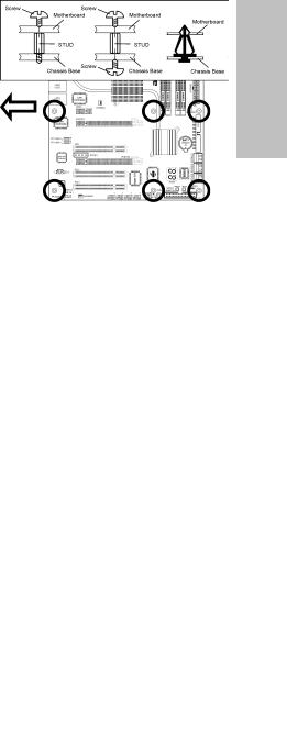
1.4 Installing Motherboard
Most computer chassis have a base with many mounting holes to allow the motherboard to be securely attached, and at the same time, prevent the system from short circuits. There are two ways to attach the motherboard to the chassis base: (1) with studs, or (2) with spacers.
Basically, the best way to attach the board is with studs. Only if you are unable to do this
should you attach the board with spacers. Line up the holes on the board with the mounting holes on the chassis. If the holes line up and there are screw holes, you can attach the board with studs. If the holes line up and there are only slots, you can only attach with spacers. Take the tip of the spacers and insert them into the slots. After doing this to all the slots, you can slide the board into position aligned with slots. After the board has been positioned, check to make sure everything is OK before putting the chassis back on.
Always power off the computer and unplug the AC power cord before adding or removing any peripheral or component. Failing to so may cause severe damage to your motherboard and/or peripherals. Plug in the AC power cord only after you have carefully checked everything.
|
To install this motherboard: |
||
|
1. |
Locate all the screw holes on the |
|
|
motherboard and the chassis base. |
||
|
2. |
Place all the studs or spacers needed on |
panel. |
|
the chassis base and have them tightened. |
||
|
3. |
Face the motherboard’s I/O ports toward |
rear |
|
the chassis’s rear panel. |
||
|
4. |
Line up all the motherboard’s screw holes |
chassis’s |
|
have them tightened. |
||
|
with those studs or spacers on the chassis. |
||
|
5. |
Install the motherboard with screws and |
|
|
To prevent shorting the PCB circuit, |
the |
|
|
please REMOVE the metal studs or |
Face |
|
|
spacers if they are already fastened |
||
|
on the chassis base and are without |
||
|
mounting-holes on the motherboard |
||
|
to align with. |
||
|
IP35 Pro |
1-3 |
Setup Hardware
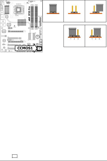
1.5 Checking Jumper Settings
•For a 2-pin jumper, plug the jumper cap on both pins will make it CLOSE (SHORT).
Remove the jumper cap, or plug it on either pin (reserved for future use) will
|
leave it at OPEN position. |
SHORT |
OPEN |
OPEN |
•For 3-pin jumper, pin 1~2 or pin 2~3 can be shorted by plugging the jumper cap in.
Pin 1~2 SHORT Pin 2~3 SHORT
1.5.1 CMOS Memory Clearing Header and Backup Battery
The time to clear the CMOS memory occurs when (a) the CMOS data becomes corrupted, (b) you forgot the supervisor or user password preset in the BIOS menu,
(c) you are unable to boot-up the system because the CPU ratio/clock was incorrectly set in the BIOS menu, or (d) whenever there is modification on the CPU or memory modules.
This header uses a jumper cap to clear the CMOS memory and have it reconfigured to the default values stored in BIOS.
•Pins 1 and 2 shorted (Default): Normal operation.
•Pins 2 and 3 shorted:
Clear CMOS memory.
To clear the CMOS memory and load in the default values:
1.Power off the system.
2.Set pin 2 and pin 3 shorted by the jumper cap. Wait for a few seconds. Set the jumper cap back to its default settings — pin 1 and pin 2 shorted.
3.Power on the system.
4.For incorrect CPU ratio/clock settings in the BIOS, press <Del> key to enter the BIOS setup menu right after powering on system.
5.Set the CPU operating speed back to its default or an appropriate value.
6.Save and exit the BIOS setup menu.
Another easy way to clear the CMOS memory can be done by switching “EZ-CCMOS1”, see the section of “Connecting Rear Panel I/O Devices” in this manual for detail.
The C.C. POST Code appears when either the external “EZ-CCMOS1” switch or the internal “CCMOS1” jumper is not set to its normal position.
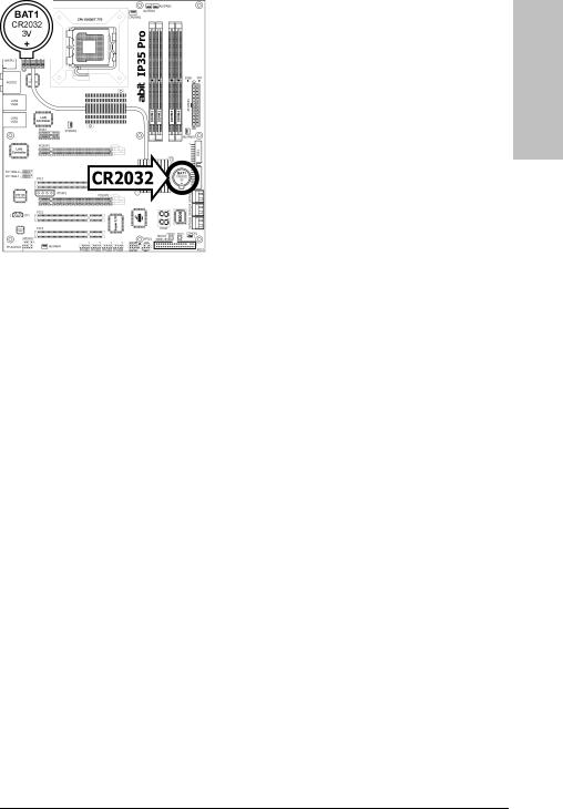
CMOS Backup Battery:
An onboard battery saves the CMOS memory to keep the BIOS information stays on even after disconnected your system with power source. Nevertheless, this backup battery exhausts after some five years. Once the error message like “CMOS BATTERY HAS FAILED” or “CMOS checksum error” displays on monitor, this backup battery is no longer functional and has to be renewed.
To renew the backup battery:
1.Power off the system and disconnect with AC power source.
2.Remove the exhausted battery.
3.Insert a new CR2032 or equivalent battery. Pay attention to its polarity. The “+” side is its positive polarity.
4.Connect AC power source and power on the system.
5.Enter the BIOS setup menu. Reconfigure the setup parameters if necessary.
CAUTION:
Danger of explosion may arise if the battery is incorrectly renewed.
Renew only with the same or equivalent type recommended by the battery manufacturer.
Dispose of used batteries according to the battery manufacturer’s instructions.
Setup Hardware
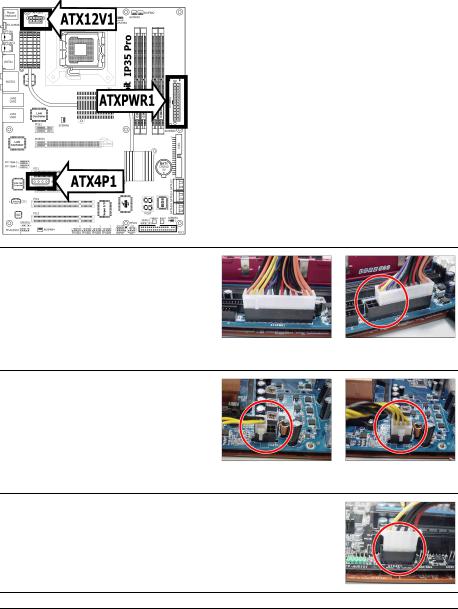
1.6 Connecting Chassis Components
1.6.1 Power Connectors
These connectors provide the connection from an ATX12V power supply. As the plugs from the power supply fit in only one orientation, find the correct one and push firmly down into these foolproof-designed connectors.
For a fully configured system, we recommend that you use a power supply of ATX12V 2.0 (or newer) specification compliant and of providing minimum 400W power output capability.
For a fully configured system with two PCI Express X16 cards installed, a power supply with minimum 500W or more power output is recommended.
The following motherboard photos are served for DEMO only, and may not be the same type or model as the one described in this user’s manual.
[ATXPWR1]: 24-pin power connector
You may connect either a 20-pin (ATX12V 1.3) or 24-pin (ATX12V 2.0) power source. However, it is recommended to connect the 24-pin ATX12V power source to meet the 240VA protection limits.
|
Plugged from a 24-pin |
Plugged from a 20-pin |
|
ATX12V power. |
ATX12V power. |
[ATX12V1]: 8-pin power connector
This connector supplies +12V power to CPU.
You may connect either a 4-pin ATX12V or an 8-pin EPS12V power source. However, it is recommended to connect the 8-pin EPS12V power source to meet the 240VA protection limits.
|
Plugged from a 4-pin |
Plugged from an 8-pin |
|
ATX12V power. |
EPS12V power. |
[ATX4P1]: Auxiliary 12V power connector
This connector provides an auxiliary power source for devices added on PCI Express slots.
![]()
1.6.2 Front Panel Switches & Indicators Headers
This header is used for connecting switches and LED indicators on the chassis front panel.
Watch the power LED pin position and orientation. The mark “+” align to the pin in the figure below stands for positive polarity for the LED connection. Please pay attention when connecting these headers. A wrong orientation will only result in the LED not lighting, but a wrong connection of the switches could cause system malfunction.
•HLED (Pin 1, 3):
Connects to the HDD LED cable of chassis front panel.
•RST (Pin 5, 7):
Connects to the Reset Switch cable of chassis front panel.
•SPKR (Pin 13, 15, 17, 19):
Connects to the System Speaker cable of chassis.
•SLED (Pin 2, 4):
Connects to the Suspend LED cable (if there is one) of chassis front panel.
•PWR (Pin 6, 8):
Connects to the Power Switch cable of chassis front panel.
•PLED (Pin 16, 18, 20):
Connects to the Power LED cable of chassis front panel.
Setup Hardware
1.6.3 FAN Power Connectors
These connectors each provide power to the cooling fans installed in your system.
•CPUFAN1: CPU Fan Power Connector
•SYSFAN1: System Fan Power Connector
•AUXFAN1~4: Auxiliary Fan Power Connector
Either a 3-pin or 4-pin CPU cooling fan connected to the “CPUFAN1” connector is still capable of having its fan speed controlled. Please refer to the BIOS setup route: “PC Health Status” “ABIT FanEQ Control” “CPU FAN Type” to select the one of your own.
These fan connectors are not jumpers. DO NOT place jumper caps on these connectors.
1.7 Installing Hardware
DO NOT scratch the motherboard when installing hardware. An accidental scratch of a tiny surface-mount component may seriously damage the motherboard.
In order to protect the contact pins, please pay attention to these notices:
1.A maximum 20 cycles of CPU installation is recommended.
2.Never touch the contact pins with fingers or any object.
3.Always put on the cap when the CPU is not in use.
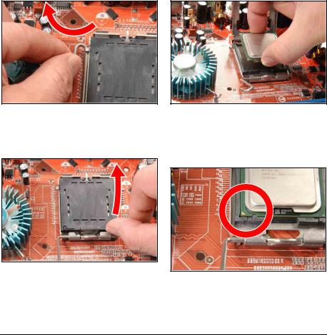
1.7.1 CPU Socket 775
The installation procedures vary with different types of CPU fan-and-heatsink assembly. The one shown here is served for demo only. For detailed information on how to install the one you bought, refer to its installation guidelines.
1. Place the board so that the lever-hook of the socket is on your left side. Use your left thumb and forefinger to hold the lever hook, pull it away from the retention tab. Rotate the lever to fully open position.
3. Use your right thumb and forefinger to grasp the CPU package. Be sure to grasp on the edge of the substrate, and face the Pin-1 indicator toward the bottom-left side. Aim at the socket and place the CPU package vertical down into the socket.
2. Use your right-thumb to raise the load plate. Lift it up to fully open position.
4. Visually inspect if the CPU is seated well into the socket. The alignment key must be located in the notch of package.
Setup Hardware
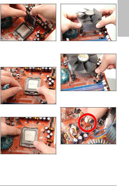
5. Use your left hand to hold the load plate, and use your right thumb to peel the cap off.
The cap plays an important role in protecting contact pins. In order to prevent bent pin, PUT ON the cap after operation or testing.
6. Lower the plate onto the CPU package. Engage the load lever while gently pressing down the load plate.
7. Secure the lever with the hook under retention tab.
8. Place the heatsink and fan assembly onto the socket. Align the four fasteners toward the four mounting holes on the motherboard.
9. Press each of the four fasteners down into the mounting holes. Rotate the fastener clock-wise to lock the heatsink and fan assembly into position.
10. Attach the four-pin power plug from the heatsink and fan assembly to the CPU FAN connector.
A higher fan speed will be helpful for better airflow and heat-dissipation. Nevertheless, stay alert to not touch any heatsink since a high temperature generated by the working system is still possible.
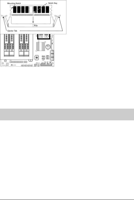
1.7.2 DDR2 Memory Slots
To reach the performance of Dual Channel DDR2, the following rules must be obeyed:
•For a 2-DIMM dual-channel installation:
Populate DIMM modules of the same type and size on slots [DIMM1]+[DIMM3], or slots [DIMM2]+[DIMM4].
•For a 4-DIMM dual-channel installation:
Populate 2 DIMM modules of the same type and size on slots [DIMM1]+[DIMM3], and another 2 DIMM modules of the same type and size on slots [DIMM2]+[DIMM4].
[DIMM1] and [DIMM3] slots are made of the same color. [DIMM2] and [DIMM4] are made of another same color.
Usually there is no hardware or BIOS setup requires after adding or removing memory modules, but you will have to clear the CMOS memory first if any memory module related problem occurs.
To install system memory:
1.Power off the computer and unplug the AC power cord before installing or removing memory modules.
2.Locate the DIMM slot on the board.
3.Hold two edges of the DIMM module carefully, keep away from touching its connectors.
4.Align the notch key on the module with the rib on the slot.
5.Firmly press the module into the slots until the ejector tabs at both sides of the slot automatically snap into the mounting notch. Do not force the DIMM module in with extra force as the DIMM module only fits in one direction.
6.To remove the DIMM modules, push the two ejector tabs on the slot outward simultaneously, and then pull out the DIMM module.
Static electricity can damage the electronic components of the computer or optional boards. Before starting these procedures, ensure that you are discharged of static electricity by touching a grounded metal object briefly.

1.7.3 PCI Express X16 Add-on Slots (Install Graphics Card)
This motherboard provides dual PCI Express X16 slots for one or two graphics cards installation of graphics cards that comply with PCI Express specifications.
One PCI Express graphics card installation:
Insert your PCI Express graphics card into slot [PCIEXP1].
Do not install only one PCI Express graphics card on slot [PCIEXP2], for such an act will pull its speed down to x4 only.
Two PCI Express graphics cards installation:
Install the master graphics card into slot [PCIEXP1]. Install the slave graphics card into slot [PCIEXP2].
Both the graphics cards must be of the same GPU family.
Make sure your power supply is sufficient to provide the minimum power required. (For a fully configured system with two PCI Express X16 cards installed, a power supply with minimum 500W or more power output is recommended.)
Refer to the instruction guide that came with the graphics card on how to run its dual display mode.
Setup Hardware
1.8 Connecting Peripheral Devices
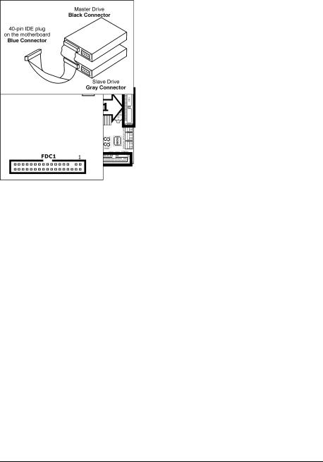
1.8.1 Floppy and IDE Disk Drive Connectors
The FDC1 connector connects up to two floppy drives with a 34-wire, 2-connector floppy cable. Connect the single end at the longer length of ribbon cable to the FDC1 on the board, the two connectors on the other end to the floppy disk drives connector. Generally you need only one floppy disk drive in your system.
The red line on the ribbon cable must be aligned with pin-1 on both the FDC1 port and the floppy connector.
Each of the IDE port connects up to two IDE drives at Ultra ATA/100 mode by one 40-pin, 80-conductor, and 3-connector Ultra ATA/66 ribbon cables.
Connect the single end (blue connector) at the longer length of ribbon cable to the IDE port of this board, the other two ends (gray and black connector) at the shorter length of the ribbon cable to the connectors of your hard drives.
Make sure to configure the “Master” and “Slave” relation before connecting two drives by one single ribbon cable. The red line on the ribbon cable must be aligned with pin-1 on both the IDE port and the hard-drive connector.
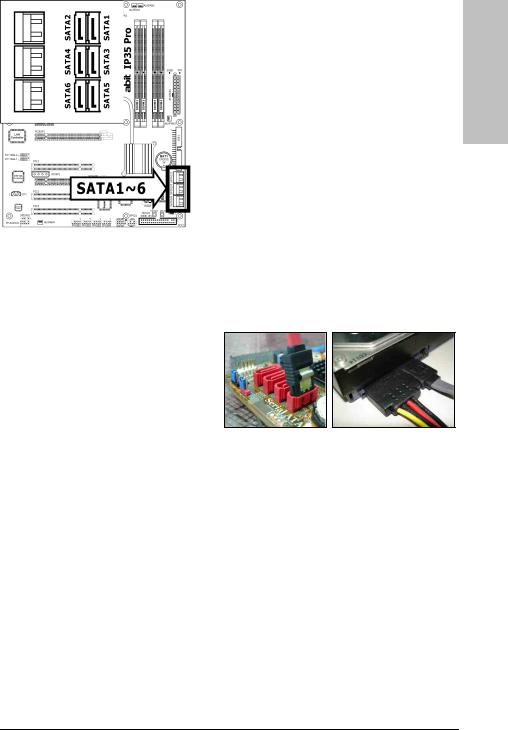
1.8.2 Serial ATA Connectors
Each SATA connector serves as one single channel to connect one SATA device by SATA cable.
To connect SATA device:
1.Attach either end of the signal cable to the SATA connector on motherboard. Attach the other end to the SATA device.
2.Attach the SATA power cable to the SATA device and connect the other end from the power supply.
The motherboard in this photo is served for DEMO only, and may not be the same type or model as the one described in this user’s manual.
Setup Hardware
1.8.3 Additional USB 2.0 Port Headers
Each header supports 2x additional USB 2.0 ports by connecting bracket or cable to the rear I/O panel or the front-mounted USB ports of your chassis.
|
Pin |
Pin Assignment |
Pin |
Pin Assignment |
|
1 |
5VDUAL |
2 |
5VDUAL |
|
3 |
Data0 — |
4 |
Data1 — |
|
5 |
Data0 + |
6 |
Data1 + |
|
7 |
Ground |
8 |
Ground |
|
10 |
NC |
Make sure the connecting cable bears the same pin assignment.
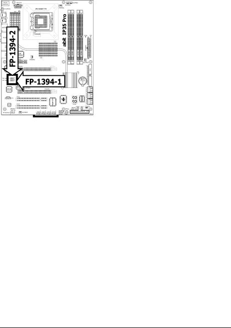
1.8.4 Additional IEEE 1394 Port Headers
Each header supports 1x additional IEEE 1394 port by connecting bracket or cable to the rear I/O panel or the front-mounted IEEE 1394 port of your chassis.
|
Pin |
Pin Assignment |
Pin |
Pin Assignment |
|
1 |
TPA0 + |
2 |
TPA0 — |
|
3 |
Ground |
4 |
Ground |
|
5 |
TPB0 + |
6 |
TPB0 — |
|
7 |
+12V |
8 |
+12V |
|
10 |
Ground |
Make sure the connecting cable bears the same pin assignment.
1.8.5 Internal Audio Connector
This connector connects to the audio output of internal CD-ROM drive or add-on card.
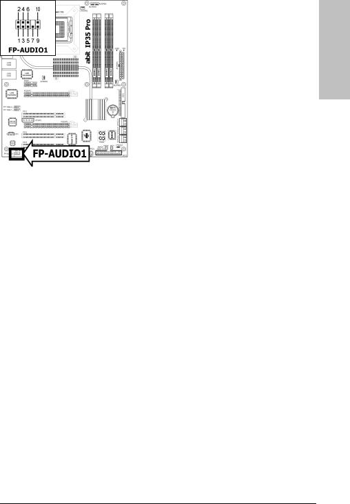
1.8.6 Front Panel Audio Connection Header
This header provides the front panel connection for HD (High Definition) Audio, yet for AC’97 Audio CODEC connection, you must carefully check the pin assignment before connecting from the front panel module. An incorrect connection may cause malfunction or even damage the motherboard.
Please do not connect the “Ground” cable or “USB VCC” cable from the front panel module to the Pin 4 “AVCC” of this header.
Setup Hardware
|
Pin |
Pin Assignment |
|
(HD AUDIO) |
|
|
1 |
MIC2 L |
|
2 |
AGND |
|
3 |
MIC2 R |
|
4 |
AVCC |
|
5 |
FRO-R |
|
6 |
MIC2_JD |
|
7 |
F_IO_SEN |
|
9 |
FRO-L |
|
10 |
LINE2_JD |
|
Pin |
Pin Assignment |
|
(AC’97 AUDIO) |
|
|
1 |
MIC In |
|
2 |
GND |
|
3 |
MIC Power |
|
4 |
NC |
|
5 |
Line Out (R) |
|
6 |
NC |
|
7 |
NC |
|
9 |
Line Out (L) |
|
10 |
NC |
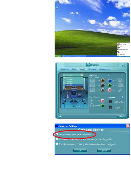
Driver Configuration for AC’97 audio connection:
The audio driver is originally configured to support HD Audio. For AC’97 audio connection, you may:
1.Right-click the “Realtek HD
Audio Manager” icon  in system tray.
2.Click “Audio I/O” tab, and then click “Connector Settings”.
3.Click “Disabled front panel jack detection”, and then click “OK” to confirm.
![]()
1.8.7 S/PDIF Output Connection Header
This header provides the S/PDIF output connection to your add-on HDMI VGA card.
|
Pin |
Pin Assignment |
|
1 |
VCC (5V) |
|
2 |
x |
|
3 |
S/PDIF Out |
|
4 |
Ground |
1.8.8 PCI and PCI Express X1 Slots
Install PCI Express X1 cards into slot “PCIE1”.
Install PCI cards into slots “PCI1”, “PCI2”, and/or “PCI3”.
Setup Hardware
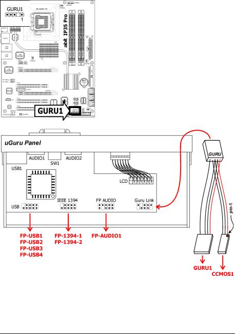
1.8.9 Guru Panel Connection Header
This header is reserved for connecting abit’s exclusive Guru Panel. For more information, please refer to the included Guru Panel Installation Guide.

1.9 Onboard Indicators and Buttons
1.9.1 POST Code Displayer
This is an LED device to display the “POST” Code, the acronym for Power On Self Test. The computer will execute the POST action whenever you power on the computer. The POST process is controlled by the BIOS. It is used to detect the status of the computer’s main components and peripherals. Each POST Code corresponds to different checkpoints that are also defined by the BIOS in advance. For example, “memory presence test” is an important checkpoint and its POST Code is “C1”. When the BIOS execute any POST item, it will write the corresponding POST Code into the address 80h. If the POST passes, the BIOS will process the next POST item and write the next POST Code into the address 80h. If the POST fails, we can check the POST Code in address 80h to find out where the problem lies.
This LED device also displays the “POST” Code of AC2005, an “uGuru” chipset developed exclusively by abit.
The decimal point lights up during the AC2005 POST action.
See Appendix for both AWARD and AC2005 POST Code definitions.
Setup Hardware
1.9.2 Power Source Indicators
•3VSB: This LED lights up when the power supply is connected with power source.
•VCC: This LED lights up when the system power is on.
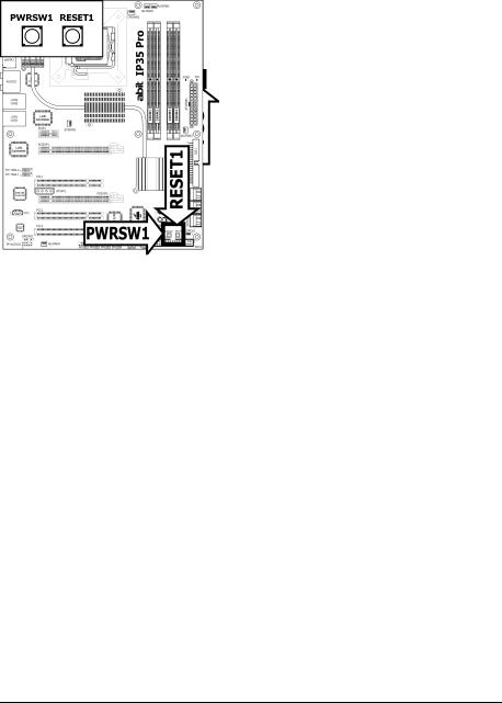
1.9.3 Onboard Buttons
•PWRSW1: Push this button to power on the system.
•RESET1: Push this button to reset the system.
1.10 Connecting Rear Panel I/O Devices
The rear I/O part of this motherboard provides the following I/O ports:
Setup Hardware
•Mouse: Connects to PS/2 mouse.
•Keyboard: Connects to PS/2 keyboard.
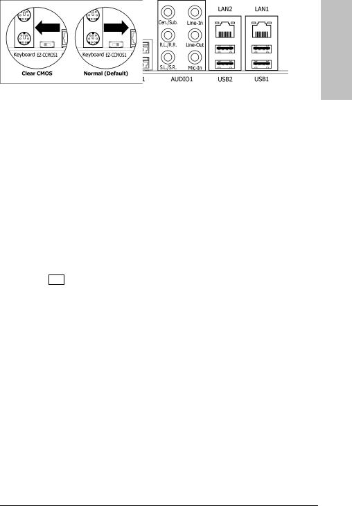
•EZ-CCMOS1: This switch enables clearing the CMOS memory without uncovering the system chassis.
To clear the CMOS memory by EZ-CCMOS1:
Step 1: Power off the system.
Step 2: Turn left this switch to the “Clear CMOS” position.
Step 3: Turn right this switch to its default “Normal” position. The default CMOS memory is now reloaded.
The C.C. POST Code appears when either the external “EZ-CCMOS1” switch or the internal “CCMOS1” jumper is not set to its normal position.
•OPT-IN1: This connector provides an S/PDIF-In connection through optical fiber from digital multimedia devices.
•OPT-OUT1: This connector provides an S/PDIF-Out connection through optical fiber to digital multimedia devices.
•eSATA1: This connector supports the external SATA connection.
•AUDIO1:
Cen./Sub. (Center / Subwoofer): Connects to the center and subwoofer channel. R.L./R.R. (Rear Left / Rear Right): Connects to the rear left and rear right channel.
S.L./S.R. (Surround Left / Surround Right): Connects to the surround left and surround right channel.
Line-In: Connects to the line out from external audio sources. Line-Out: Connects to the front left and front right channel. Mic-In: Connects to the plug from external microphone.
•LAN1/LAN2: Connects to Local Area Network.
•USB1/USB2: Connects to USB devices such as scanner, digital speakers, monitor, mouse, keyboard, hub, digital camera, joystick etc.

2. BIOS Setup
This motherboard provides a programmable EEPROM so that you can update the BIOS utility. The BIOS (Basic Input/Output System) is a program that deals with the basic level of communication between processor and peripherals. Use the BIOS Setup program only when installing motherboard, reconfiguring system, or prompted to “Run Setup”. This chapter explains the Setup Utility of BIOS utility.
After powering up the system, the BIOS message appears on the screen, the memory count begins, and then the following message appears on the screen:
PRESS DEL TO ENTER SETUP
If this message disappears before you respond, restart the system by pressing <Ctrl> + <Alt> + <Del> keys, or by pressing the Reset button on the computer chassis. Only when these two methods fail should you restart the system by powering it off and then back on.
After pressing <Del> key, the main menu screen appears.
Phoenix – AwardBIOS CMOS Setup Utility
|
► |
uGuru Utility |
► PnP/PCI Configurations |
|
► |
Standard CMOS Features |
Load Fail-Safe Defaults |
|
► |
Advanced BIOS Features |
Load Optimized Defaults |
|
► |
Advanced Chipset Features |
Set Password |
|
► |
Integrated Peripherals |
Save & Exit Setup |
|
► |
Power Management Setup |
Exit Without Saving |
|
Esc: Quit |
: Select Item |
|
|
F10: Save & Exit Setup |
(P35-W627DHG-6A790A1BC-00) |
|
|
F6 : Save PROFILE To BIOS |
F7 : Load PROFILE From BIOS |
Change CPU’s Clock & Voltage
In order to increase system stability and performance, our engineering staff is constantly improving the BIOS menu. The BIOS setup screens and descriptions illustrated in this manual are for your reference only, and may not completely match with what you see on your screen.
Setup BIOS
инструкцияabit IP35 PRO XE

Hardware Setup
BIOS Setup
Driver & Utility Multilingual QIG Appendix
Motherboard
Socket 775
User’s Manual
About this Manual:
This user’s manual contains all the information you may
need for setting up this motherboard. To read the user’s
manual of PDF format (readable by Adobe Reader), place
the “Driver & Utility CD” into the CD-ROM drive in your
system. The auto-run screen will appear, click the
Manual” tab to enter its submenu. If not, browse the
root directory of the CD-ROM via the File Manager, and
double click the “AUTORUN” file.
Intel P35 / ICH9R
FSB 1333 MHz
Dual Channel DDR2 800
Dual PCI-E X16 Slots
Dual Gigabit LAN
6x Internal, 2x External SATA
3Gb/s Connectors
USB 2.0 / IEEE 1394
7.1-Channel HD Audio
abit uGuru™
Technology
abit Silent OTES™ Technology
External CMOS Clearing
Switch
Quick Power & Reset Button
Vista Premium HW Ready
Посмотреть инструкция для abit IP35 PRO XE бесплатно. Руководство относится к категории Материнские платы, 2 человек(а) дали ему среднюю оценку 8.5. Руководство доступно на следующих языках: английский. У вас есть вопрос о abit IP35 PRO XE или вам нужна помощь? Задайте свой вопрос здесь
- 1. Hardware Setup
Главная
| abit | |
| IP35 PRO XE | IP35 PRO XE | |
| Материнская плата | |
| 4710933355240 | |
| английский | |
| Руководство пользователя (PDF) |
Память
| без функции коррекции ошибок | Да |
| Максимальная внутренняя память | 8 GB |
| Количество слотов памяти | 4 |
Процессор
| Производитель процессора | Intel |
| Сокет процессора | LGA 775 (Socket T) |
| Поддерживаемые системные шины процессора | 1600 MHz |
Внутренние порты
| Число коннекторов SATA | 4 |
| Разъемы USB 2.0 | 4 |
| Количество разъемов IEEE 1394 | 2 |
| Количество параллельных разъемов ATA (PATA) | 1 |
| Аудиоразъем передней панели | Да |
Порты на задней панели
| Количество портов PS/2 | 2 |
| Количество портов USB 2.0 | 4 |
| Порты FireWire | 0 |
| Количество портов Ethernet LAN ( RJ-45) | 1 |
| Линейные выходы наушников | 1 |
| Линейный вход микрофона | Да |
| Порт выхода S/PDIF | Да |
| Количество портов VGA (D-Sub) | 0 |
| Количество портов eSATA | 0 |
| Количество портов DVI-D | 0 |
| Количество HDMI портов | 0 |
Свойства
| Формат материнской платы | ATX |
| Выходные звуковые каналы | 7.1 канала |
| Тип источника питания | ATX |
Слоты расширения
| PCI Express x16 слоты | 2 |
| PCI слоты | 3 |
| PCI Express x1 слоты | 1 |
Вес и размеры
| Ширина | 305 mm |
| Глубина | 245 mm |
Прочие свойства
| Тип (2-ого) интерфейса контроллера | ATA 133/100/66/3 IDE |
| Тип интерфейса контроллера | SATA |
| Порты ввода/вывода | 1 x FP-Audio |
| Тип контроллера RAID | SATA |
Сеть
| Характеристики сети | Gigabit LAN |
показать больше
Не можете найти ответ на свой вопрос в руководстве? Вы можете найти ответ на свой вопрос ниже, в разделе часто задаваемых вопросов о abit IP35 PRO XE.
Не нашли свой вопрос? Задайте свой вопрос здесь
Hardware Setup
BIOS Setup
Driver & Utility
Multilingual QIG
Appendix
IP35 Pro
Motherboard
About this Manual:
This user’s manual contains all the information you may
need for setting up this motherboard. To read the user’s
manual of PDF format (readable by
Adobe Reader
), place
the “Driver & Utility CD” into the CD-ROM drive in your
system. The auto-run screen will appear, click the
“Manual” tab to enter its submenu. If not, browse the
root directory of the CD-ROM via the File Manager, and
double click the “AUTORUN” file.
Intel P35 / ICH9R
FSB 1333 MHz
Dual Channel DDR2 800
Dual PCI-E X16 Slots
Dual Gigabit LAN
6x Internal, 2x External SATA
3Gb/s Connectors
USB 2.0 / IEEE 1394
7.1-Channel HD Audio
abit uGuru™
Technology
abit Silent OTES™ Technology
External CMOS Clearing
Switch
Quick Power & Reset Button
Vista Premium HW Ready
7793
Views
4
Replies
4
Participants
Last post by
wuyanxu,
Jump to Latest
Just got myself an IP35 Pro and I hooked everything up and to begin with, it wont power on. It has a post code indicator LED (cooool…) on it and I get a code of 0.1. In my users manual the post code of 0.1 reads as «Expand the Xgroup codes locating in physical address 1000:0» …what the hell does that mean?
Solved my problem. …Don’t know exactly how I did it, but the thing turned on…and has the same problem I have always had: Windows Vista 64 BSODs after about 2 minutes. Can’t wait for my replacement Vista disk to get here so that I can do a repair.
the BIOS post code is in the white manual, last few pages.
- This is an older thread, you may not receive a response, and could
be reviving an old thread. Please consider creating a new thread.